AVENAR panel Installation | en 49
Bosch Sicherheitssysteme GmbH
System manual
2022-07 | 5.0 | F.01U.378.910
1. Monitor with 4-wire end of line element:
– On stub cabling, terminate the exposed end of an AUX line with an FLM-420-EOL4W
– Insert an FLM-420-EOL4W as the last element of an LSN ring or of a stub
– Use an FLM-320-EOL4W-S for the conventional zone of a conventional zone module
or a FLM-420/4‑CON
2. In FSP-5000-RPS, activate operation with extended line monitoring (formerly EN 54-13
requirement, now VdS 2540 and VdS 2543 requirement).
Notice!
VdS 2540, VdS 2543
For extended line monitoring (creeping short circuit and creeping open monitoring), no
branch wiring is permitted for auxiliary power supplies.
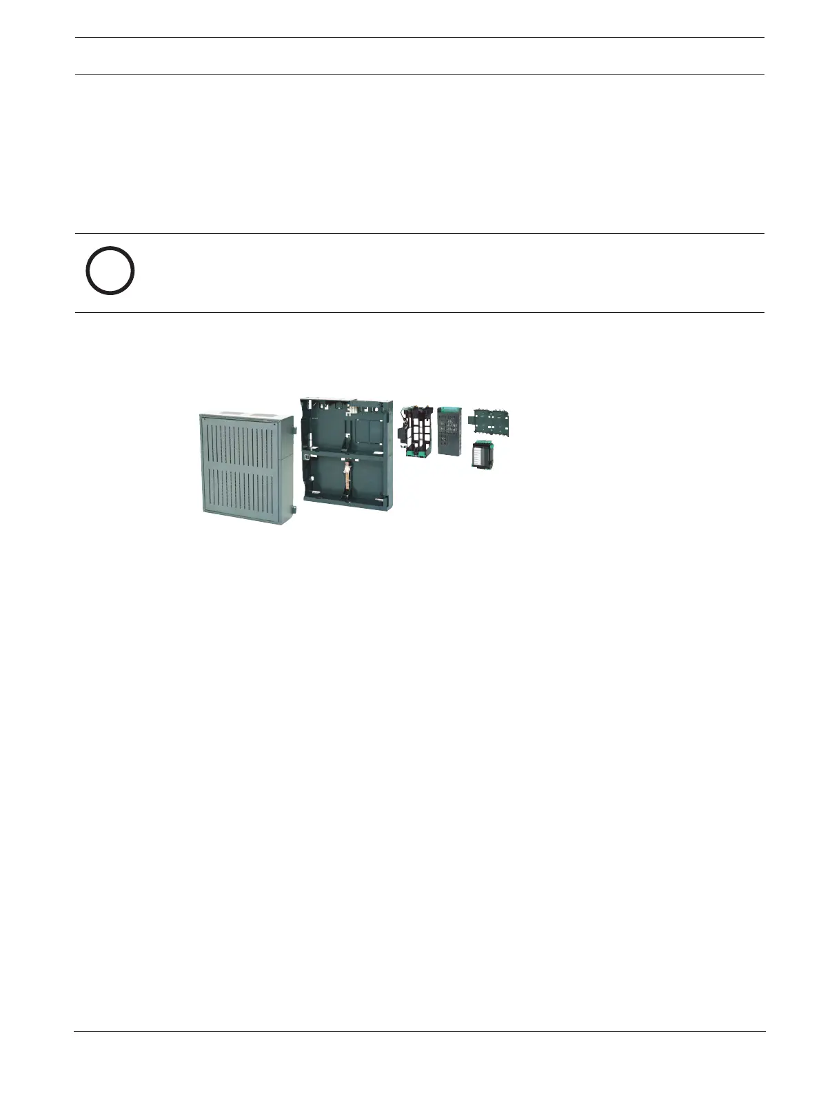
4.6 FPP‑5000 External Power Supply Unit Kit 24V/6A
The FPP-5000 External Power Supply Unit Kit is designed to provide a universal power supply,
and has space for two 12V/45Ah batteries.
Figure4.3: FPP‑5000 External Power Supply Unit Kit 24V/6A
Scope of Delivery
– PMF 0002 A Power Supply Housing Frame Installation medium
– FMH 0000 A Mounting Frame Medium
– Power supply bracket, installed
– UPS 2416 A Universal Power Supply
– PRS-0002-C Panel Rail Short
– BCM-0000-B Battery Controller Module
– Requisite cable sets
Can be Extended with:
– 2 x 12V/45Ah batteries
– FPP‑5000‑TI Trouble Interface or FPP-5000-TI13 LSN Communication Interface
– FPO‑5000‑EB Earth Bar
Notes
– You can find the installation instructions for the FPP-5000 kit at www.boschsecurity.com
by searching for the type designation (document number for installation instructions:
F.01U.005.065).
– The installation dimensions are the same as those for the PMF 0004 A with FMH 0000 A
Mounting frame.
FPP‑5000‑TITrouble Interface
The FPP-5000-TImodule is used in the FPP-5000 External Power Supply Unit with the
BCM-0000-B to transmit faults to the fire panel via the Local Security Network (LSN).
Two independent signal inputs for "battery fault" and "mains current fault" allow a specified
fault indication on the fire panel.