Configuration
FlexibleAutomation
2−4
2.1.1 Card Cages
A variety of card cages can be used for the CL300 Programmable Controller and its
expansions to suit application specific requirements.
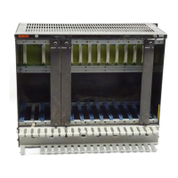
2.1.1.1 Card Cage BGT301
The BGT301 Card Cage is a 19" metal rack to accommodate 14 modules in dual
Eurocard format. The lower part of the BGT301 offers additional space to install a fan
unit. The cable duct, which swings open on the front side, is placed transversely on
the lower front. A perforated mounting bracket is attached on each side of the
BGT301. The upper side of the card cage has louvers to ensure heat dissipation of
the CL300.
Power for the individual modules is supplied internally by the power supply unit via a
bus bar integrated in the card cage. The modules communicate via the buses con
tained in the card cage:
D PERIPHERAL BUS and
D SYSTEM BUS
The system bus runs from slot 3 to slot 6, permitting to accommodate 3 intelligent
system modules in slots 4, 5, and 6 in addition to the central processing unit ZE301.
Slots 7 to 14 are designed for the accommodation of peripheral modules. With dis
tributed expansion, slot 7 is provided for the expansion module AG/DZ . The follow
ing illustrations show the BGT301 Card Cage, its partitioning and dimensions.
Ordering Information Order No.
Card Cage BGT301 052003
Cable Duct 054152
Filler Panel, 1 module width 046208