Page 16 P/N: 4998152533-02 Copyright 2007 Bosch Security Systems, Inc. DS7200V2-UK Installer's Guide
PART II: SYSTEM INSTALLATION AND SETUP
15.0 On-board Sensor Loop Setup
15.1 Overview
The control panel provides eight on-board dual EOL
(End-of-Line) sensor loops (L-1 to L-8). Each sensor
loop operates independently and does not interfere
with the operation of the others.
15.2 Tamper-wired Zone Configuration
The on-board sensor loops can be used as tamper-
wired zones to report tamper conditions when the
zone has become open or shorted.
See Figure 10 when wiring a sensor loop as a
tamper-wired zone.
Alarm
Contact
Tamper Contact
Sensor Loop
1-8
Com
2.2 k
EOL
2.2 k EOL
Figure 10: Tamper-Wired Zone Wiring
When the tamper-wired zones are used, some
configuration types can be used without any EOL
resistors. See Location ##, Zone Function on page 76
for information on special tamper-wired zone
configuration options.
15.3 No EOL Zone Configuration
See Figure 11 when wiring a zone with no EOL
resistors.
Zone Input
Terminal
Common
Normally Closed Contacts
L-1 to L-8
Zone Input
Terminal
Common
Normally Open Contacts
100 ohms maximum
Figure 11: Single Zone Sensor Loop Wiring (No EOL)
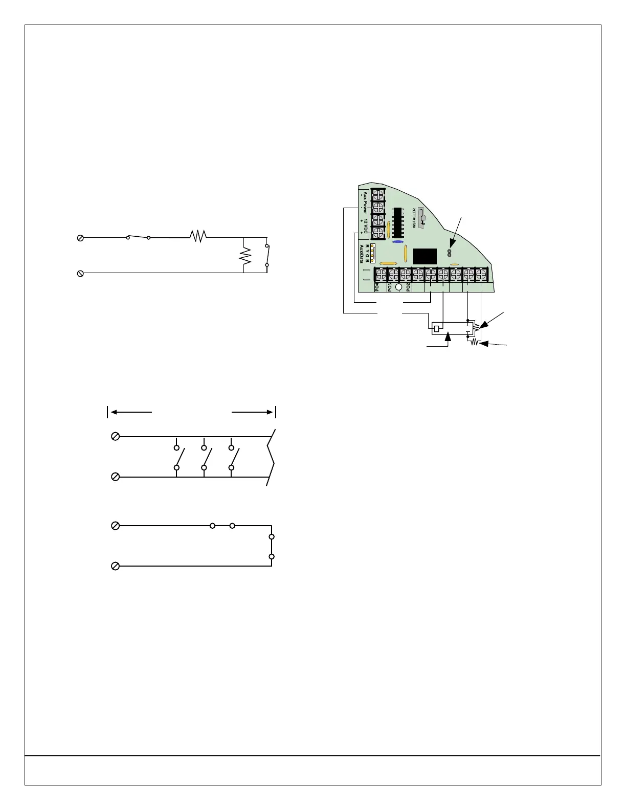
15.4 Four-wire Smoke Detector Configuration
A four-wire smoke detector can be connected to any
of the control panel’s on-board sensor loops (L-1 to L-
8). A four-wire smoke detector requires the use of a
relay module to interrupt power to the detector in
order for the detector to reset.
The output controlling the relay must be configured as
Output Function 1|13 Fire Verification (see Outputs on
page 86 for more information).
Make loop connections to L-X (where X = Loop #) and
“COM” terminals.
Remove PO 1 SELECT Jumper
2.2 k
Ω
Alarm
Resistor
2.2 k
Ω
EOL
Resistor
Smoke Detector
BATT+
BATT-
ALRM
+
PO1
SMK
+
PO1 SELECT
Aux (+)
A B COM
Aux (-)
L-1
Figure 12: 4-wire Smoke Detector (Tamper-wired)
16.0 On-board Output Setup
16.1 Overview
There are four on-board programmable outputs on the
panel (PO 1 to PO 4).
Programmable Output 2 (PO 2) can be configured as
a supervised siren driver. See Global Output
Configuration on page 84 for programming
instructions. When programmed as a siren driver, PO
2 draws power from the ALRM + terminal. When
connected to a 4 Ω horn/speaker, PO 2 draws 380
mA of current. When connected to an 8 Ω
horn/speaker, it draws 330 mA of current. Use the
appropriate current draw in your total alarm current
calculation.