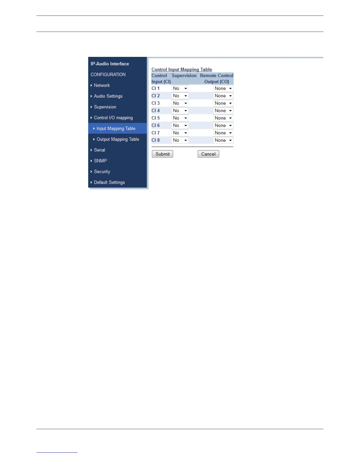
Control Input Mapping Table
Figure 6.9: Control Input Mapping Table screen (default)
Defaults: No/None
In the Control Input Mapping Table for each of the Control Inputs the Supervision can be
enabled and a response defined.
If Supervision is enabled for an input, then two 10 kohm resistors should be connected at the
far end, close to the switch or relay that is triggering this input, see Multiple Unicast, page 14.
If Supervision is not enabled, then the input can be connected directly to a switch or relay,
without resistors. The operation of the Control Input is the same, but no unintentional open or
short circuits can be detected anymore, as these are interpreted as normal trigger signals.
Each Control Input activation can be use to activate one of the eight Control Outputs of the
connected partner devices. Please note that this activation is edge triggered and not level
triggered, so multiple Control Inputs can activate the same Control Output, but the Control
Output is de-activated as soon as one of Control Inputs is deactivated.
Submit / Cancel button
Submit saves the set values, restarts the device and returns back to the last screen. Cancel
restores the last submitted values.
6.2.8
IP Audio Interface Configuration | en 29
Bosch Security Systems B.V. Operating Manual 2013.03 | V2.0 |