Derating in case of deviating ambient conditions
A permanent use of the motors is possible when
the specified class 3K22 according to EN IEC
60721-3-3:2019 is observed. Deviations and
enhancements according to the follwing table
must be observed.
Table 13: Ambient conditions
Operation
Installation altitude 0 … 1,000 m above MSL
Ambient temperature 0 … +40 °C
Relative humidity 5 … 95 %
Absolute humidity 1 … 29 g/m
3
8.3.1
Vibration load during opera-
tion
Vibrations are sine-wave oscillations in stationary
use, which vary in their effect on the resistance of
the motors depending on their intensity.
The specified limit values are valid for frequen-
cies of 10‑2000 Hz during stimulation on the
motor flange. Limitations can be necessary for
occurring resonances depending on the applica-
tion and installation situation.
The following limit values apply according to
EN 60068-2-6 for MS2N motors:
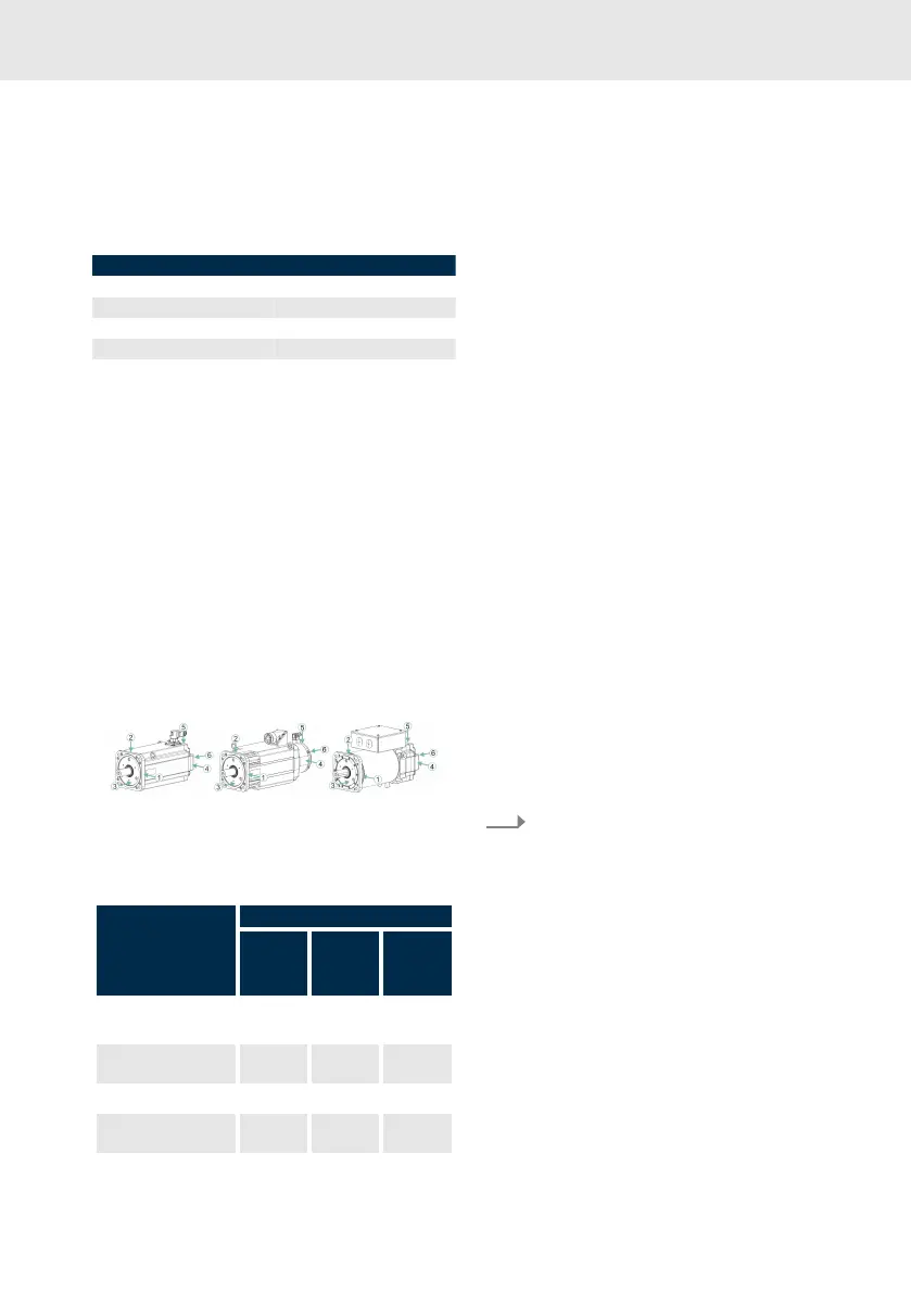
Fig. 33: Vibration load on measuring points
Table 14: Permissible vibration load for MS2N
motors
Measuring point, direc-
tion
Limit value (10-2000 Hz)
Motors
Self-
cooling
Motors
Forced
ventilation
Motors
Water
cooling
1, 2 (radial motor
flange)
30 m/s² 10 m/s² 10 m/s²
4, 5 (radial bearing
shield / fan)
50 m/s² 25 m/s² 25 m/s²
3 (axial motor flange) 10 m/s² 10 m/s² 10 m/s²
6 (axial bearing shield /
fan)
25 m/s² 25 m/s² 25 m/s²
Check the vibration load on the fan housing in
case of forced ventilation. The specified values
must not be exceeded.
8.4 Operation
During operation, keep the ambient and opera-
tion conditions and technical data specified in
the project planning manual.
Checks during operation:
•
Pay attention to exceptional noise.
• Pay attention to increased vibrations.
• Check the motors and fan units for cleanli-
ness.
• Check the tightness of the coolant connec-
tions.
• Check the monitoring devices and diag-
nostic / error messages of the controllers.
Decommission the drive when deviations from
normal operation exist. For further procedure
refer to .
8.5
Derating in case of devi-
ating ambient conditions
Reduce high performance data:
1.
Reduce the standstill torque M
0 60K
or
M
0 100K
specified in the data sheet, with
the following factors.
We have:
M
0 red
= M
0 60K
× f
TH 60K
M
0 red
= M
0 100K
× f
TH 100K
M
0 red
= M
0 100K
× f
TH W