11 | Analog and Frequency Inputs
54/136 Vehicle_Control_Unit_VCU_Manual Bosch Motorsport
Input pin Pull-up
resistor is
activated
Sensivity and
Offset value
for sensor
Adjustment
is enabled
Channel is linked
to ANA04
Pin Diagnosis
Name and
Description
editable
Available measurements for channel:
Measurement label Function
raw_name mV value of sensor
raw_name_fi filtered mV value of sensor
name physical value of sensor
name_fi filtered physical value
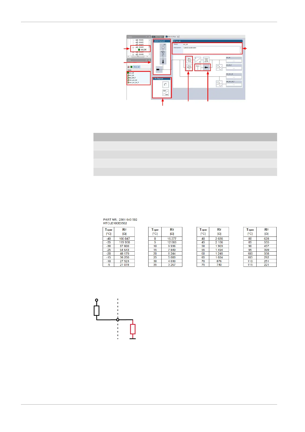
11.2.3 Configuring a generic nonlinear sensor
Example: Thermistor 5 kOhm
– From sensor data sheet - resistance values over temperature:
– The sensor has a nonlinear behavior
– Use characteristic curve for linearization
– Input voltage is the ratio between pull-up resistor and thermistor
1. Click ‘Measurement Sources’ in the Toolbox.
2. To expand the list of ‘I/O Channels’, click on ‘+’ in the Vehicle Control Unit VCU Pro-
ject Tree.
3. Drag the “Characteristic Curve” analogue signal source from the Toolbox and drop it
on the desired analogue input channel in the Vehicle Control Unit VCU Project Tree.