Pre-Installation
Worcester 2000 – 6 721 814 551 (2019/09)
12
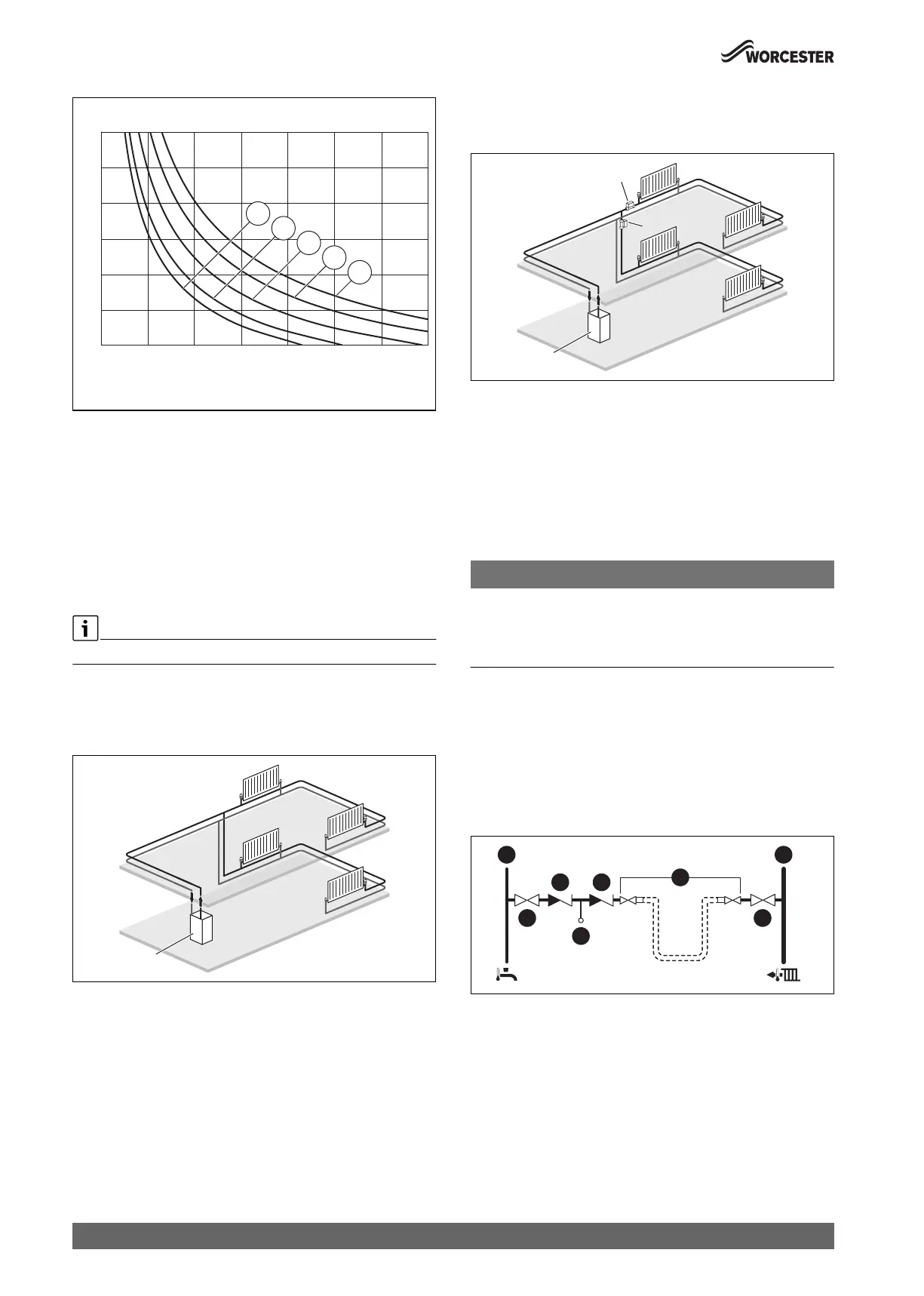
Fig. 5 Curves for the expansion vessel
1 Pre-charge pressure 0.5 bar (minimum)
2 Pre-charge pressure 0.75 bar
3 Pre-charge pressure 1.0 bar
4 Pre-charge pressure 1.2 bar
5 Pre-charge pressure 1.3 bar
A Operational capacity of the expansion vessel (left of the relevant
curve)
B Additional expansion vessel required (right of the relevant curve)
T Maximum operating temperature [ °C]
V Total System Volume [l]
The default pre-charge pressure for the appliance is 0.75 bar
4.1.3 System layouts examples
Sealed primary system - Single central heating circuit:
Typical primary system example
Fig. 6 Single central heating circuit example
[1] Appliance
Sealed primary system - 2 x central heating zones:
• Requirement for new builds if the floor area of a property is over
150m
2
.
Fig. 7 Separated heating zones
[1] Appliance
[2] Zone valves
4.1.4 System fill
Integral filling link
• An optional filling link accessory is available to fill the system.
– Refer to filling link instructions for fitting and operation.
Filling primary sealed systems
NOTICE:
Filling the primary sealed system
The system must not be filled with salt based softened water.
▶ Ensure the primary water filling point uses an untreated cold water
connection from the mains supply, before a water softener.
• Filling the system must comply with one of the following methods
shown.
• The filling point must be at low level and must never be a permanent
connection to the mains water supply.
• Filling loops must be WRAS approved.
• If the external filling link is sited away from the appliance, then a
pressure gauge should be installed at the filling point.
External filling loop
Fig. 8 External filling loop system fill example
[1] Cold mains inlet pipe
[2] Stop valve
[3] Check valve
[4] Test point
[5] Hose union
[6] Central heating flow pipe
0010016558-002
A
B
4
5
3
2
1
30
40
50
60
70
80
90
0 100 200 300 400 500
600 700
T[°C]
V[l]
1
0010021227-002
1
2
2
0010021228-002
0010012942-001
6
22
4
3 3
1
5
 Loading...