Installation
31
Worcester 2000 – 6 721 814 551 (2019/09)
Rear flue outlet [2].
▶ Mark centre line of flue to be used; the external diameter of the hole
can also be marked if required.
▶ If extensions are to be added then the complete flue must rise at an
angle of 3° from the appliance.
Side flue outlet [1].
▶ Mark from the centre line of the wall mounting template to the wall
which the flue will pass through.
▶ Allow for a rise of 52mm per metre length of flue, to give a 3° angle.
Example hole size.
• If a 60/100mm diameter flue is to be used, a 125mm diameter hole
is required.
• If using the weather sealing collar by pushing it through from inside
the property, then a 150mm diameter hole is required to
accommodate this.
Flue outlet position marked and ready to drill hole.
▶ Drill hole using a core drill or similar.
▶ Clear any debris from the site.
Appliance fixings and flue outlet drilled and ready.
▶ Remove the wall mounting template.
Fig. 37 Wall mounting template
1 Side exit flue example
2 Rear exit flue example
3 Wall mounting template
4 Primary fixing points
D 125mm
5.2 Appliance connections
WARNING:
Appliance - gas connection
▶ Ensure the mains gas supply is isolated before starting any work
and follow all relevant safety precautions.
NOTICE:
Appliance - hydraulic connections
▶ Ensure all water pipe work, to be connected, are isolated/drained
and follow all relevant safety precautions.
▶ Be careful of plastic components when using a naked flame on pipe
work.
Surplus water may be present inside the appliance due to factory testing.
External condensate pipe work or internal pipe runs in unheated areas
such as lofts, basements and garages exposed to prolonged cold
temperatures should be protected chapter 4.5.
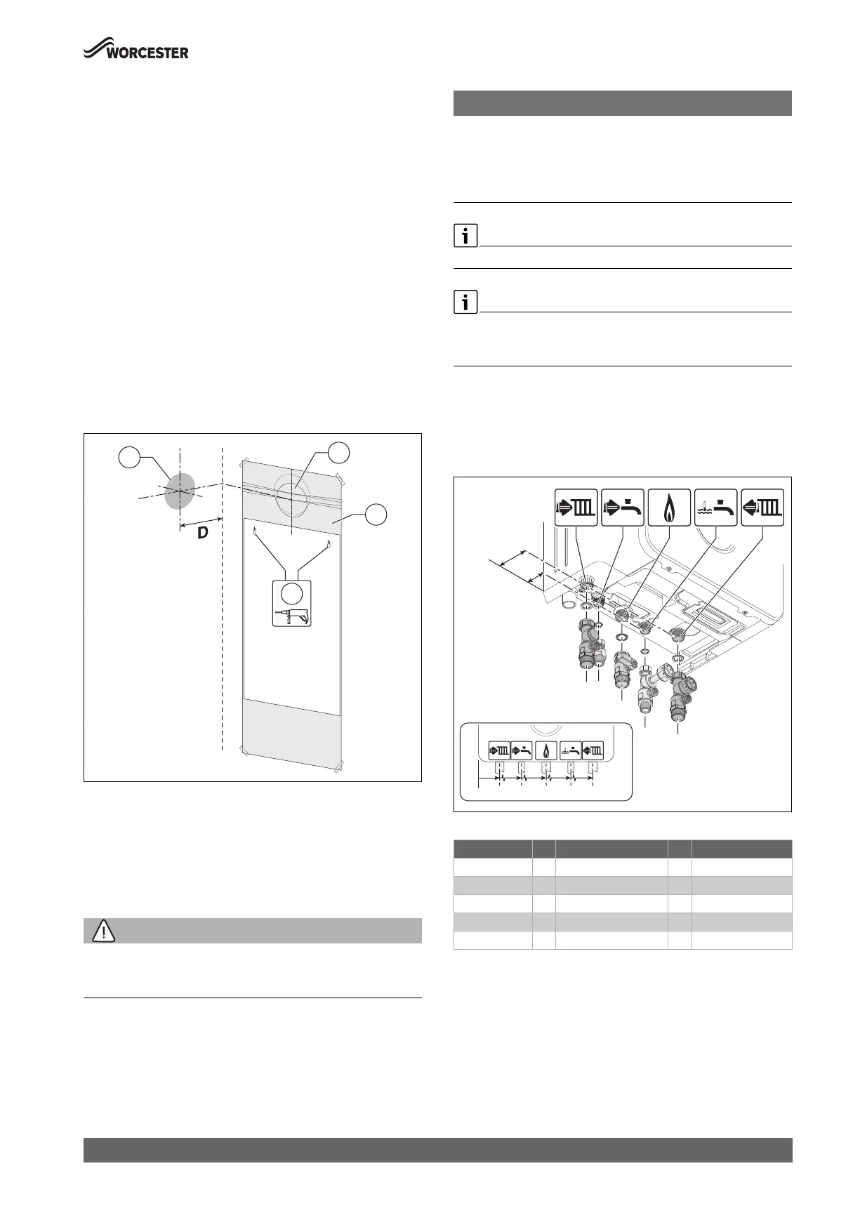
Connection sets fitting
Installing the connection sets
Refer to figure 38.
▶ Ensure the sealing washers are fitted in the connection sets before
installing the connection sets.
Fig. 38 Fitting the connection sets
Table 15
▶ Connect the heating, domestic water and gas pipe work to the
respective compression adaptor on the connection sets.
0010029478-001
2
3
4
1
Description # From left case edge # From wall
CH flow 1 68mm 6 60mm
DHW outlet 2 133mm 7 30mm
Gas 3 200mm 7 30mm
DCW Inlet 4 267mm 7 30mm
CH return 5 332mm 6 60mm
##########-001
7
6
12 3 45
 Loading...