Pre-Installation
Worcester 2000 – 6 721 814 551 (2019/09)
18
Vertical balanced flue with 90° elbow offset
Fig. 22 Vertical flue option
• Flue length [L]
– Maximum flue length as stated in "Vertical maximum flue lengths"
minus 2 x 90° bends equivalent straight flue length as stated in
Table 13 "Effective length of bends".
Vertical balanced flue with 45° elbow offset
Fig. 23 Vertical flue option
• Flue length [L]
– Maximum flue length as stated in "Vertical maximum flue lengths"
minus 2 x 45° bends equivalent straight flue length as stated in
Table 13 "Effective length of bends".
4.4.3 Plume management system
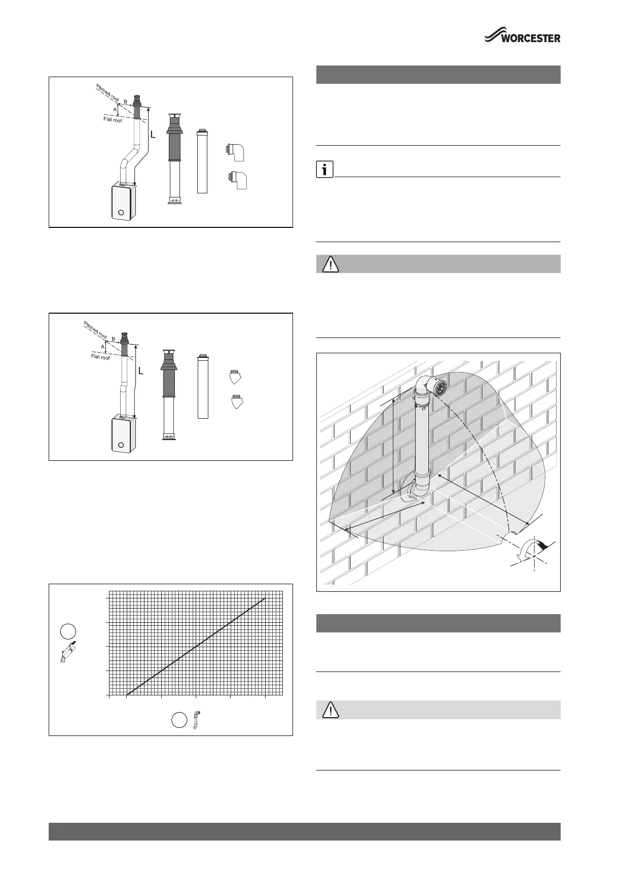
For every extra 1,000mm of plume management after the first 500mm,
the internal 60/100 flue length must be reduced by 700mm, up to a
maximum of 4,500mm of plume management.
Fig. 24 Reduction to flue length as plume length increases graph
[1] Reduction to flue length [mm] (maximum reduction 2,800mm)
[2] Plume length [mm] (maximum plume length 4,500mm)
NOTICE:
Plume management length:
▶ The plume management length must be a minimum of 500mm and
must not exceed the maximum straight length for a horizontal Ø 60/
100mm flue with a 60mm plume management system as stated
previously.
Horizontal plume management runs
▶ The initial horizontal run from the terminal elbow must have a
minimum 10° fall back, (stop tabs in the elbow prevent less than 10°)
to the appliance for proper disposal of condensate.
▶ Any further horizontal runs after an elbow can be 3°.
WARNING:
Minimum plume management length:
The minimum distance of 500mm must be maintained between air inlet
and exhaust.
▶ Do not terminate the plume management inside the terminal
exclusion zone (shaded area) shown in figure 25.
Fig. 25 Terminal exclusion zone
NOTICE:
Cutting the 500mm pipe
▶ The Plume management extension kit contains the components
required for such a configuration.
4.4.4 Flue terminal positions
CAUTION:
Flue terminal positions
▶ All measurements are the minimum clearances required.
▶ Terminals must be positioned so to avoid combustion products
entering the building.
0010015200-001
= 300 mm
B = 500 mm
0010015201-001
= 300 mm
B = 500 mm
0010023114-001
0
700
1,400
2,100
2,800
500 1,500 2,500 3,500 4,500
[mm]
[mm]
2
1
0010013548-001
5
0
0
m
m
5
00
mm
5
00
m
m
±80°
 Loading...