Commissioning
41
Worcester 2000 – 6 721 814 551 (2019/09)
Gas pressure within the system
The appliance must be running at maximum output rate when
performing the gas rate check, ( chapter 6.5.1).
Combi appliances
▶ Running a hot water tap does not guarantee the boiler will operate at
maximum output throughout the test.
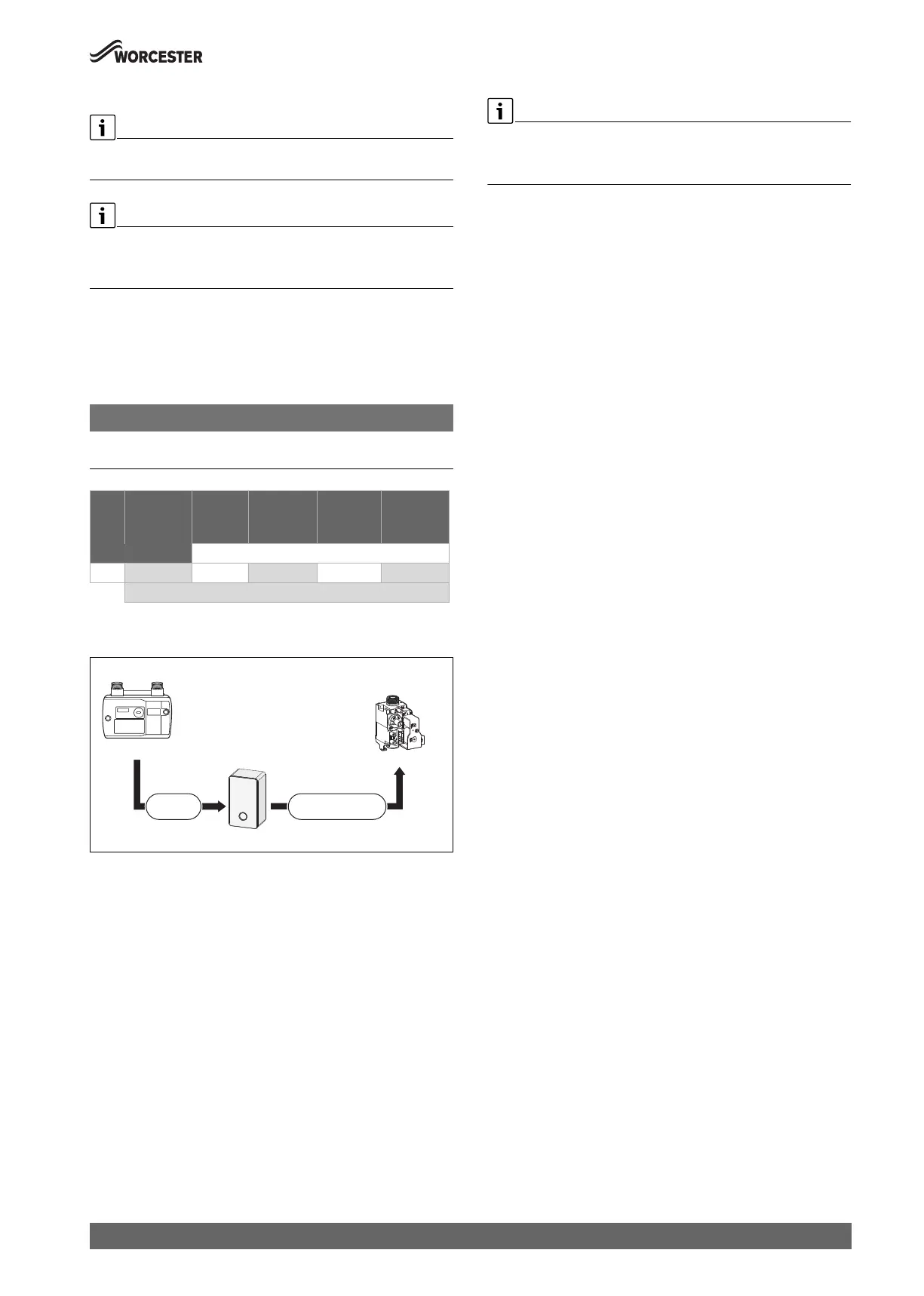
Refer to the figures below for Natural Gas gas pressures.
The pressure drop from the meter to the gas valve inlet test point must
not be more than the values stated in table 20.
If the pressure drops are greater than shown in table 20, then this would
indicate a problem with the pipe work or connections within the system.
NOTICE:
Do not continue commissioning until the correct gas pressure is
achieved.
Table 20 Allowed mbar pressure drop
Gas supply pressure drop
Fig. 55 Natural Gas pressures
[A] Pressure loss across the appliance
[B] Pressure reading at inlet test point
6.7 Checking the gas rate
▶ The gas rate should be measured at the gas meter after the appliance
has been operating for a minimum of 10 minutes at maximum output.
▶ Refer to Technical data section of this manual for the appliance gas
rates and CO/CO
2
ratios.
▶ Gas rate must be checked with the appliance in service, maximum
output test mode.
▶ Carry out Gas rating procedures as described in current edition of the
“Essential Gas Safety”.
▶ Ensure all other gas appliances are isolated when carrying out the gas
rate check on the appliance.
Maximum output mode
▶ A hot water outlet can be opened to prevent the appliance from
shutting down due to high temperature during testing.
▶ Ensure all other gas appliances are isolated.
▶ Press the ok button until the C symbol appears on the display.
The display shows the maximum percentage of the power 100%
alternating with the flow temperature.
▶ Ensure that the appliance has stabilised at maximum output.
▶ If pressure and gas rate are satisfactory press the ok button and the
appliance will return to normal operation.
– If left in the service mode the control will return to normal
operation after 30 minutes.
▶ Close the gas isolation valve.
▶ Remove the manometer.
▶ Re-seal the screw in the gas inlet pressure test point.
▶ Open the gas isolation valve.
▶ Ensure that there are no gas leaks.
6.8 Checking for gas leaks during operation
▶ Use an approved gas leak detector to check all connections for
possible leaks. The product must be certified as a gas leak testing
agent.
▶ Do not allow the product to come into contact with the electrical
wiring.
Gas
Type
Meter Across
pipe
work
Appliance
inlet
Across
appliance
[A]
Gas valve
inlet test
point [B]
Allowed mbar pressure drop
NG 19 - 23 1 18 - 22 1.5 16.5 - 20.5
mbar range
0010012820-001
Natural Gas
Appliance inlet
18 - 22 mbar
Meter
19 - 23 mbar
Gas Control
valve
Inlet test point [B]
1.0 mbar
drop
Across appliance
drop [A]
 Loading...