Installation
35
Worcester 2000 – 6 721 814 551 (2019/09)
5.5.1 Installer connections
Component access
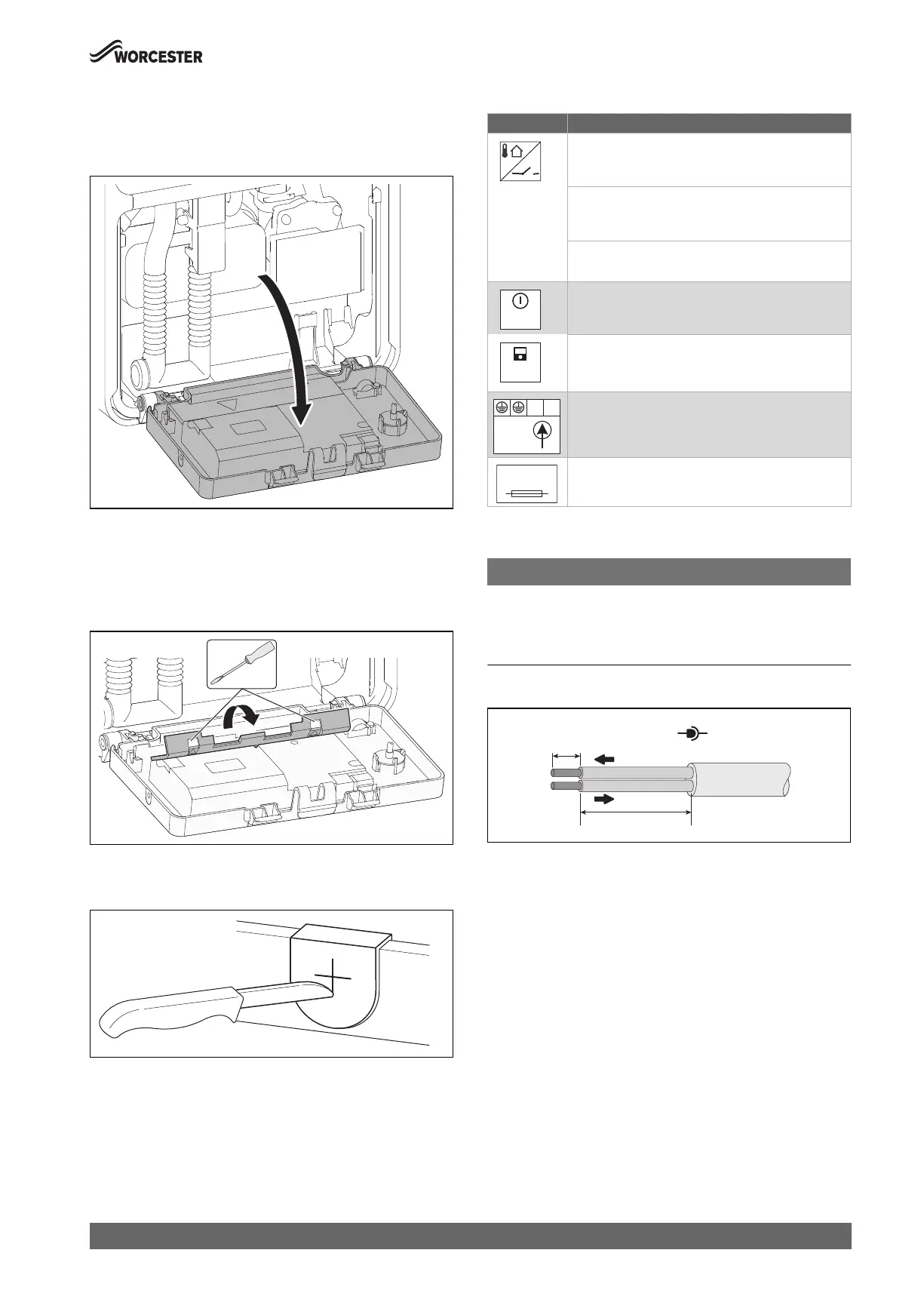
▶ Release catch and hinge open the control panel into the service
position.
Fig. 46 Moving control panel into service position
Connect external accessories
▶ Release the latches using a thin bladed screwdriver. Arrows on the
electrical cover indicate the position where the screw driver must be
inserted to release the catches.
▶ Open the rear cover.
Fig. 47 Open the cover
▶ For splash protection (IP): Cut the strain relief according to the
diameter of the cable.
Fig. 48 Cable feed
▶ Guide the cable through the strain relief.
▶ Connect the cable to the terminal block for external accessories.
▶ Secure the cable to the strain relief.
External accessories terminal strip
Table 16 Terminal strip for external accessories
5.5.2 Cable preparations
NOTICE:
Damage to control unit!
Small pieces of wire can cause shorts and damage to electronics.
▶ When stripping wires always ensure copper strands do not fall into
the control box.
Low voltage (signal cables), example figure 49
Fig. 49 Low voltage (signal cables) preparation
0010022207-001
0010029486-001
0010029485-001
Symbol Function
Outside temperature sensor or ON/OFF temperature
controller. (link factory fitted)
The outside temperature sensor for the user interface
is connected to the device.
▶ Connect the outside temperature sensor.
ON/OFF temperature controller
No functionality; not used
No functionality; not used
(link factory fitted)
External user interface/external module with 2-wire
BUS.
▶ Connect communication cable.
Mains connection (power cable)
Fuse
I3
BUS
NL
230V
IN
Fuse
5AF
0010012956-001
26-30mm
6-8mm
0-30V
 Loading...