Installation
33
Worcester 2000 – 6 721 814 551 (2019/09)
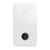
Connect condensate discharge pipe
▶ Connect the condensate discharge pipe to the appliance condensate
hose outlet connection.
Fig. 42 Connecting to the condensate outlet connection
[1] Condensate hose outlet connection
[2] Condensate discharge pipe
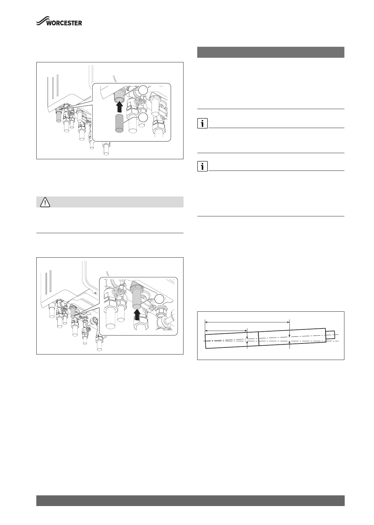
Connect PRV discharge pipe
CAUTION:
Risk of damage to appliance!
Only use compression fitting when connecting to the PRV tail.
▶ Do not solder to the PRV tail connection.
▶ Connect the PRV discharge pipe to the appliance PRV tail via
compression fitting (not supplied).
Fig. 43 Connecting to the PRV tail connection
[1] PRV tail connection
5.4 Flue turret/adaptor installation
NOTICE:
Flue installation
▶ Refer to the Flue Kit Installation instructions provided with your flue
kit to correctly install the flue with this appliance.
▶ Do not exceed the maximum straight length for a horizontal or vertical
flue or a 60mm plume management system (if used) as stated in the
relevant Installation and Maintenance Instructions manual or
addendum.
Telescopic flue
▶ Cutting the flue to an exact measurement is not required as the
telescopic flue terminal can allow for some adjustment.
Apply silicone lubricant to sealing surfaces, to ease assembly of flue
components.
Refer to the manual supplied with the flue kit for complete installation
instructions.
▶ For plume management effective lengths and the effective flue
lengths, chapter 4.4.
Additional notes and reminders:
• Ensure that all cut lengths are square and free from burrs.
• Ensure that the flue and seals are not damaged.
• The flue is sealed when assembled correctly, the components are
pushed fully home and secured.
• The flue rises from the appliance at an angle of 3° or 52mm per metre
length.
• Support the flue at each flue extension joint and at each change of
direction, use suitable brackets and fittings:
– Flue bracket 100mm part number: 7 716 191 177.
– Flue brackets 100mm x 6 part number: 7 716 191 178.
– Flue bracket 125mm part number: 7 716 191 179.
Fig. 44 Slope for condensate disposal
Refer to figure 45.
▶ Remove the three inner flue tube retaining screws [1].
– The inner tube will be held in place in the appliance.
▶ Check the appliance flue seal [2] is correctly seated and apply
silicone grease.
Flue turret [A] fitting
▶ Align the flue turret [A] to the appliance flue outlet with flat facing [3]
to the rear of the appliance.
– This should be pushed straight down, on to the appliance.
▶ The three inner flue tube retaining screws [1] are, re-used to secure
the flue turret [A].
Vertical adaptor [B] fitting
▶ Align the vertical adaptor [B] to the appliance flue outlet with flat
facing [3] to the rear of the appliance.
– This should be pushed straight down, on to the appliance.
0010029707-001
1
2
0010029713-001
1
104mm52mm
2,000mm
1,000mm
0010013472-001
 Loading...