Inspection and maintenance
53
Worcester 2000 – 6 721 814 551 (2019/09)
9.7 Checking the flue integrity
NOTICE:
▶ Check flue joints are secure, the terminal and the terminal guard, if
fitted are clear and undamaged.
▶ Combustion testing must be carried out by a competent person.
Testing must not be attempted unless the person carrying out the
combustion check is equipped with a calibrated Flue Gas Analyser
conforming to BS 7967 and is competent in its use.
Flue gas analysis
▶ Ensure that the gas inlet pressure has been checked and is
satisfactory.
▶ Refit the test point plugs after the test has been completed.
▶ Refer to section 6.10 "Checking flue integrity" and check that the
readings conform to those given, confirming flue system and
combustion circuit are ok.
9.8 Cleaning the siphon and heat exchanger
WARNING:
Gaskets and seals - gas related components
▶ Burner/electrode assembly gasket must be replaced if disturbed
▶ Other gaskets/seals must be checked and replaced where necessary
▶ Do not attempt the cleaning procedure unless new gaskets and seals
are available.
9.8.1 Cleaning the heat exchanger
There is an optional tool available to assist in cleaning the heat
exchanger, part number 7 733 600 091.
Checking the electrodes and cleaning the heat exchanger
CAUTION:
Risk of burns due to hot surfaces!
Individual components of the appliance can become very hot even after
being shut down for a long time.
▶ Before working on the appliance: Allow the appliance to cool down.
▶ If necessary, wear protective gloves.
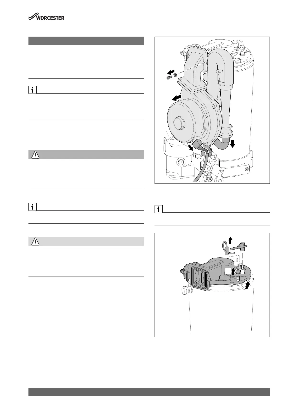
1. Unplug plug from the fan.
2. Remove the gas hose from the venturi nozzle.
3. Remove the screw on the mixing device.
4. Remove the fan with mixing device.
Fig. 62 Removing the fan with mixing device
▶ Pull off cable from the ignition and flame sense electrode.
▶ Remove the burner cover.
To ensure full tightness when assembling the burner once the
maintenance is complete, tighten the M8 nut as far as it will go.
Fig. 63 Remove the burner cover
4.
3.
1.
2.
0010016229-002
2.
1.
3.
0010015927-002
 Loading...