Technical Specifications/Logs
Worcester 2000 – 6 721 814 551 (2019/09)
76
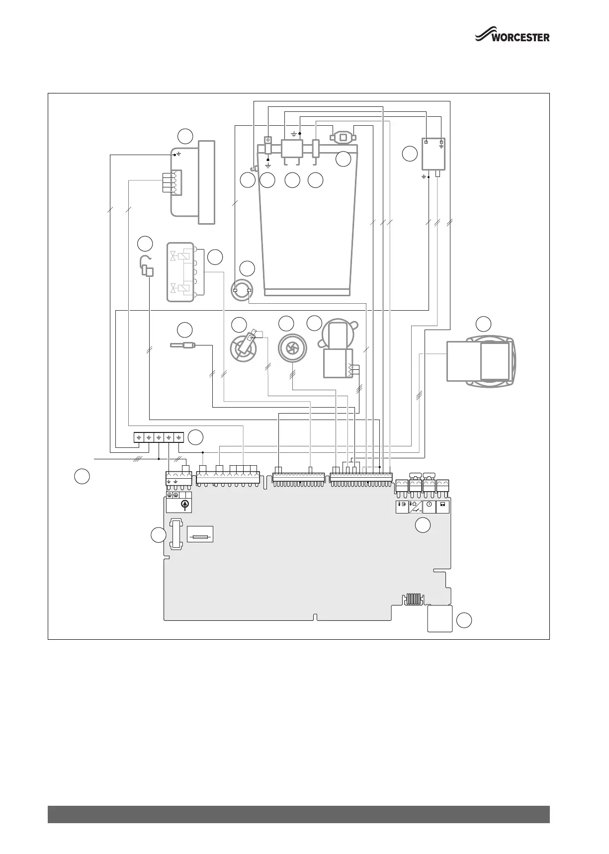
13.4 Internal wiring of the appliance
13.4.1 Electircal wiring
Fig. 95 Electrical wiring
Legend to figure 95:
[1] Fuse
[2] Mains cable
[3] Earth connections
[4] DHW temperature sensor
[5] Low water pressure switch
[6] Flow limiter cartridge
[7] Diverter valve
[8] Exhaust gas temperature limiter
[9] Gas valve
[10] Flow temperature sensor
[11] Fan
[12] Heat exchanger flow temperature sensor
[13] Earth connection
[14] Ignition electrode
[15] Flame sense electrode
[16] Heat exchanger high limit stat
[17] Ignition transformer
[18] Pump
[19] Low voltage I/Os for controls
[20] Code plug interface - Not used
0010029492-001
NL
5
N L
230V
IN
5AF
TW1
I3
BUS
11
12
10
9
8
4
5
6
7
18
3
2
1
19
20
13 14 15
16
17
230V
 Loading...