18 | Auto Changeover mode WW & WT Models
WW & WT Models8733943362 (2016/08) Subject to change without prior notice
when the unit runs after power is applied or the mode is
changed from heating to cooling, if fluid temperature is
above cooling point and does not change for 3 minutes,
the second stage of cooling will be activated. this only
applies for a two stage machine.
There will be 5 minute delay on break after the unit
cycles off on temperature, a power interruption or
because of a fault condition.
AUTO CHANGEOVER MODE
The controller’s auto change over mode control feature
will switch from the heating mode to cooling mode and
vice versa based on the setting of the change over
sensor. There will be a dead-band where the control will
not call for either heat or cool. The dead -band setting is
adjustable in the configuration mode. When the auto
changeover mode is selected the changeover set point
will be displayed for 5 seconds, however this point is
only adjustable when the controller is in the
configuration mode. Once the controller has switched to
either heating or cooling mode, pressing the up or down
buttons will display the set point for that particular
mode.
When the reading from the changeover sensor is above
the change over set point plus the dead-band setting,
the unit will operate in the cooling mode and will
maintain the cooling set point temperature. While in the
cooling mode the user can adjust the cooling set point.
Likewise when the change over sensor is below the
changeover set point minus the dead-band setting, the
unit will switch to the heating mode and will maintain
the heating set point temperature. While in the heating
mode the user can adjust the heating set point.
Once the reading from the sensor enters the
dead-band zone it will terminate the call for cooling or
heating even if the set points are not satisfied.
Mode switching will be HEAT – COOL – OFF in a closed
loop. If the changeover sensor is shorted when the
control is in Auto changeover mode then the control will
switch to the OFF mode. If no sensor is connected the
controller will indicate a sensor error code.
UNIT PROTECTION
The unit controller will protect the unit against a high or
low pressure condition and brownout. To avoid nuisance
lockouts an intelligent reset function is built into the
controller to allow the unit to restart one time in the
event of a fault condition.
If a fault condition is initiated on any circuit the
corresponding compressor will be turned off and the 5
minute delay on break time period timer is initiated.
After the delay expires the unit will attempt to restart. If
the fault condition still exists or reoccurs within the
next 60 minutes, the unit will go into a hard lockout and
requires a manual lockout reset. During this period the
fault LED will indicate the cause of the fault. A 120
second time delay is built into the low pressure switch
to avoid nuisance trips with low fluid temperatures.
While in a soft lockout condition the display will show
the specific fault (for example LP1) and the “service”
LED will turn on according to the malfunction mode. If
the setting for malfunction mode is “steady,” the service
LED will turn and remain on. If the setting is “pulse,” the
service LED will blink according to the blink code as
follows:
BROWNOUT PROTECTION
The control will disable all outputs if the supply
voltage drops below 17 VAC. The outputs will be
enabled if the supply voltage rises and remains
above 17 VAC for the 5 minutes time delay. During
that time control will display “bro.”
MANUAL LOCKOUT
The unit or refrigeration circuit will go into a manual
lockout if the HPS or LPS opens (LPS open more than
120 seconds each time) WW/WT within one hour. During
manual lockout the compressor(s) is turned off and
locked out and the display will show the fault (for
example LP1) and the “service” LED “malfunction”
output will either be steady or blink according to the
malfunction mode as described above.
If selection for compressor is “Du” (see configuration)
and one compressor has locked out, the control will
switch the call to the other compressor. If compressor
setting is “Si”, the control shall not switch the call to the
other compressor.
LEAD-LAG
The Controller has the capability to lead-lag
compressors on a dual compressor unit. The lead-lag
between the compressors is active only when both
compressors are in use (and the compressor setting is
“Du”). When the setting for lead-lag is other than 00,
compressor setting is “Du” and one compressor
has locked out; control will switch the call to the
other compressor and stop the timing for lead-lag.
The lead lag setting remains in the memory.
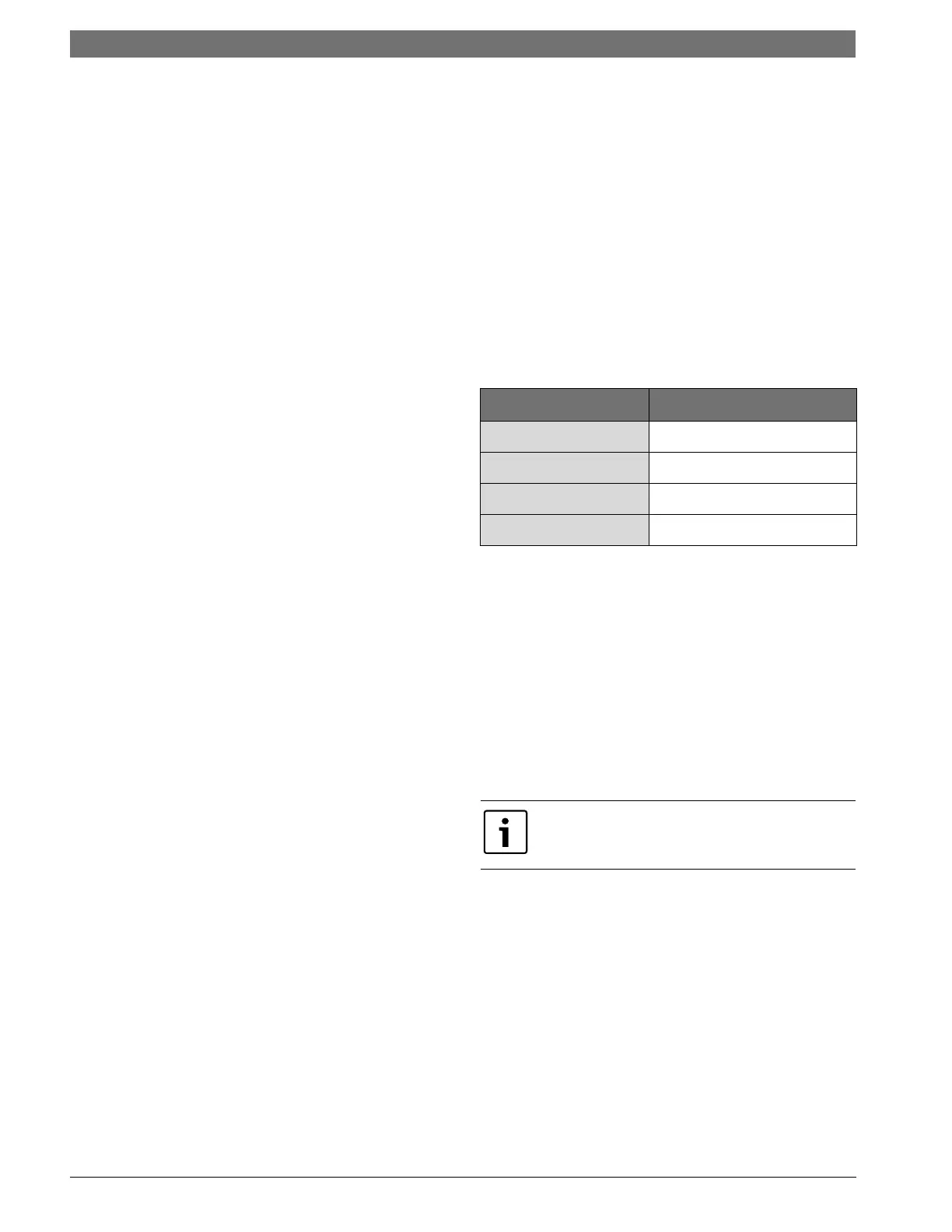
Blink Code Fault Condition
ONE BLINK
High pressure circuit 1
TWO BLINKS
Low pressure circuit 1
THREE BLINKS
high pressure circuit 2
FOUR BLINKS
Low pressure circuit 2
To reset a unit after a hard lockout the user needs to
recycle power or switch the controller to the OFF
mode.