Heat Recovery Package | 11WW & WT Models
8733943362 (2016/08)Revised 08-16
DPS Water Flow Proving
The DPS water flow proving switch is a factory installed
option available for the WW/WT series. The DPS
prevents compressor operation if there is inadequate
water flow through the water to refrigerant heat
exchanger in the heat pump.
The DPS operates by monitoring the water side pressure
drop across the water to refrigerant heat exchanger.
When the pressure drop between the water in and water
out lines reaches a pre-set value, compressor operation
is enabled.
Pump Relay
The factory installed pump relay can be used to energize
a supply pump or solenoid valve when there is a call for
compressor operation. This relay can be used to switch
either high or low voltage power.
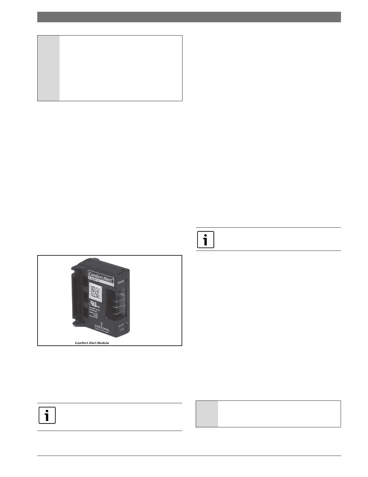
Comfort Alert Module
The Comfort Alert diagnostics module (CADM) is a
breakthrough innovation for troubleshooting heat pump
system failures. See figure #6. (available for WT only)
Figure # 6
By monitoring and analyzing data from the compressor
and the thermostat demand, the module can accurately
detect the cause of electrical and system related failures
without any sensors. A flashing LED indicator
communicates the ALERT code and guides the service
technician more quickly and accurately to the root cause
of a problem.
When an abnormal system condition occurs, the
Comfort Alert module displays the appropriate ALERT
and/or TRIP LED.
The yellow ALERT LED will flash a number of times
consecutively, pause and then repeat the process.
To identify a Flash Code number, count the number of
consecutive flashes.
Every time the module powers up, the last ALERT Flash
Code that occurred prior to shut down is displayed for
one minute.Heat Recovery Package
HEAT RECOVERY PACKAGE
Water Tank Preparation
1. Turn off electrical or fuel supply to the water heater.
2. Attach garden hose to water tank drain connection
and run other end of hose out doors or to an open
drain.
3. Close cold water inlet valve to water heater tank.
4. Drain tank by opening drain valve on the bottom of
the tank, then open pressure relief valve or hot
water faucet.
5. Once drained the tank should be flushed with cold
water until the water leaving the drain hose is clear
and free of sediment.
6. Close all valves and remove the drain hose.
7. Install HR water piping.
HR Water Piping
All hot water piping MUST be a minimum of 3/8” O.D.
copper tube to a maximum distance of fifteen (15) feet.
For distances beyond fifteen feet but not exceeding sixty
(60) feet use 1/2” copper tube. Separately insulate all
exposed surface of both connecting water lines with 3/
8” wall closed cell insulation. Install isolation valves on
supply and return to the heat recovery. (Figure #7)
Water Tank Refill
1. Open the cold water supply to the tank.
2. Open a hot water faucet to vent air from the system
until water flows from the faucet, then close.
3. Depress the hot water tank pressure relief valve
handle to ensure there is no air remaining in the
tank.
4. Carefully inspect all plumbing for water leaks.
Correct as required.
5. Purge all air from HR by depressing the schrader
valve on the HR Unit. Allow all air to bleed out until
water appears at the valve.
NOTICE: If heat recovery unit is installed in
an area where freezing may occur, the unit
must be drained during winter months to
prevent heat exchanger damage. Heat
exchanger ruptures that occur due to
freezing will void the heat recovery package
warranty along with the heat pump
warranty.
This module does not provide safety protection! The
Comfort Alert module is a monitoring device and
cannot shut down the compressor directly.
Concentric water fitting (p/n 8-733-907-779) is
recommended.
NOTICE: All piping from HRP to domestic
water tank must be copper or any metal of
stronger alloy.