Pump cycling | 19WW & WT Models
8733943362 (2016/08)Revised 08-16
If control has called for the second stage three times in
a row, and compressor setting is “Du”; regardless of the
lead-lag setting control will switch the call to the other
compressor. The lead-lag timer is reset and the lead-lag
setting still applies.
PUMP CYCLING
When ordered with the optional pump relay the
controller will cycle either the load, source or both
pumps with the compressor operation. Please see
the typical wiring diagram for details.
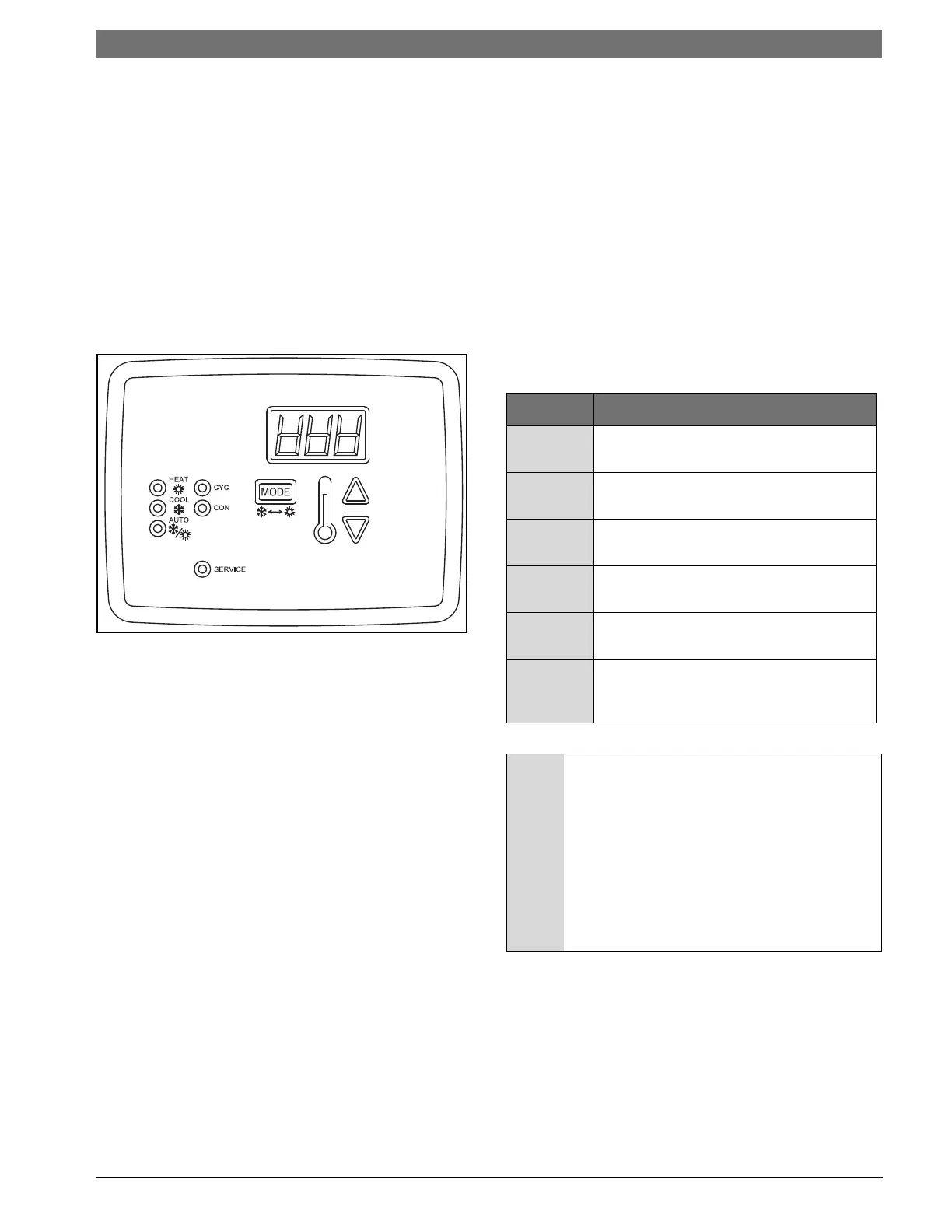
OPERATING INSTRUCTIONS
Please refer to figure #13
Figure # 12
User Interface
The following parameters are displayed on the
screen:
• Control fluid temperature when in normal mode
• Settings within the configuration mode
• Individual operating mode temperature set points
• Fault display
UP Button:
• Press once to display the current set point
temperature.
• After current set point temperature is displayed,
pressing again will increment the set point 1
degree for every push. Pressing and holding the
up button will increment the set point at a rate of
4 degrees per second.
•
When pressed with the down arrow for
5-seconds, the control will display the current
temperature scale (Fahrenheit or Celsius).
• Used to change the settings for: temperature scale,
dead band, test mode, initial delay, compressor, pump,
and malfunction settings.
DOWN Button:
• Press once to display the current set point
temperature.
• After current set point temperature is displayed,
pressing again will decrement the set point 1 degree for
every push. Pressing and holding the down button will
decrement the set point at arate of 4 degrees per
second.
• When pressed with the up arrow for 5- seconds,
the control will display the current temperature scale
(Fahrenheit or Celsius).
• Used to change the settings for: temperature scale,
dead band, test mode, initial delay, compressor, pump,
and malfunction settings.
LED Indicators
Mode Indication
HEAT Red LED to indicate that the control is
in the HEATING mode
COOL Green LED to indicate that the control
is in the COOLING mode
AUTO Yellow LED to indicate that the control
is in AUTO mode
COM Red LED to indicate that pump(s) are
selected for continuous operation
CYC Red LED to indicate that pump(s) are
selected for cycling operation
SERVICE Red LED will turn steady on or blink to
indicate that a pressure switch has
opened
NOTICE: 40° F clamp-on freeze stat located on
the water out piping, where loop temperature
is expected to go below water freezing
temperature, this stat should be removed
from the safety circuit. Based on the
application an appropriate amount of
antifreeze must be used to protect the heat
pump from freezing. The freeze stat is wired in
series with the HP switch and the same fault
code will be displayed for either condition
Refer to the Unit Wiring Diagram