8 | Electrical WW & WT Models
WW & WT Models8733943362 (2016/08) Subject to change without prior notice
UPM control (Remote T-ATAT models
only)
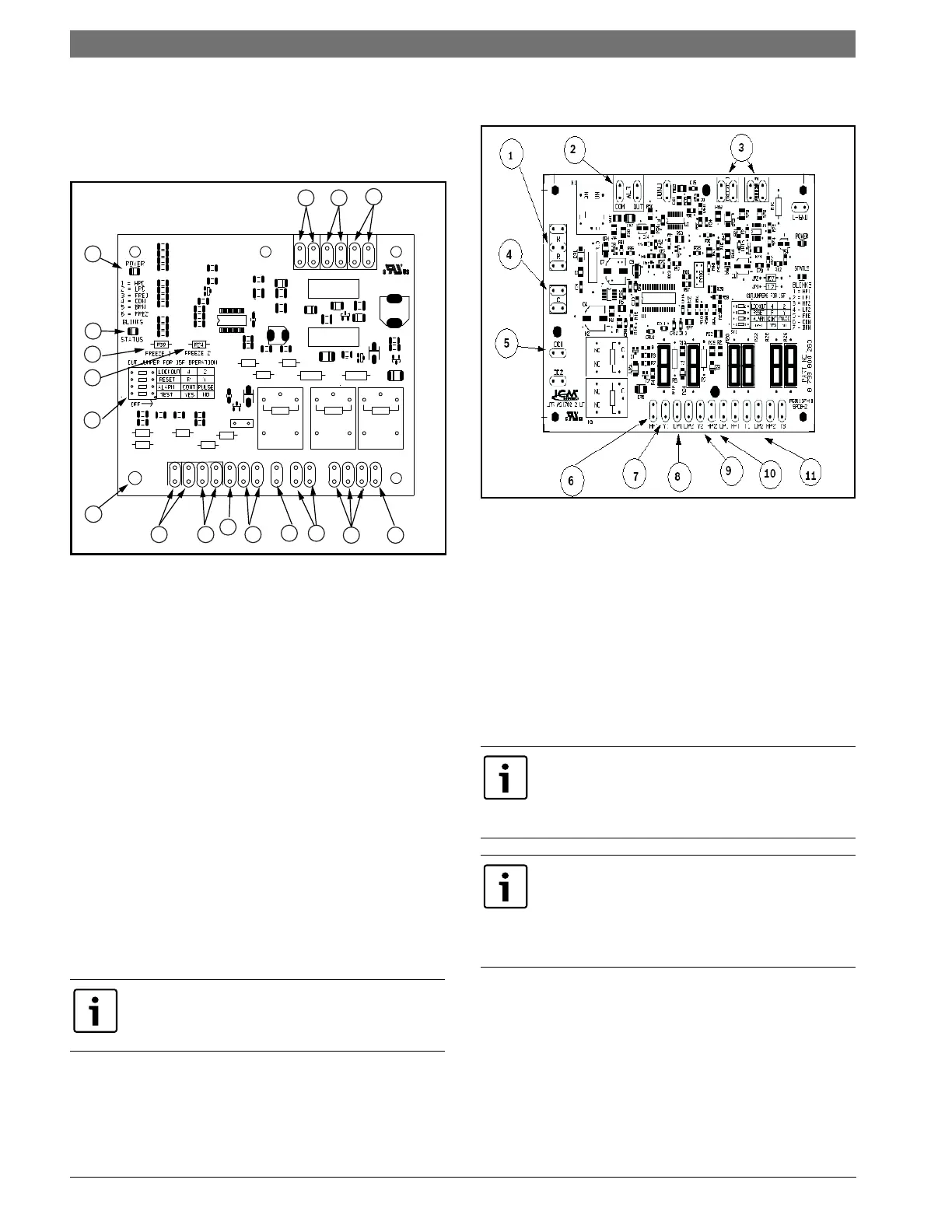
Safety Devices and the UPM I Controller
Figure # 3
[1] Board Power Indicator
[2] UPM Status LED Indicator
[3]Water Source Coil Freeze Protection Temperature
Selection [R30]
[4] Load Water Coil Freeze Protection Temperature
Selection [R24]
[5] UPM Board Settings
[6] Source Coax Freeze Connection (Freeze 1)
[7] Load Coax Freeze Connection (Freeze 2)
[8] LCD Unit Display Connection
[9] 24VAC Power Input
[10] Compressor Contact Output
[11] High Pressure Switch Connection
[12] Call for Compressor Y1
[13] Low Pressure Switch Connection
[14] 24VAC Power Common
[15] Condensate overflow Sensor (not applicable on
WW/WT)
[16] Dry Contact
[17] UPM Ground Standoff
Safety Devices and the UPM II Controller
Figure # 4
[1] Power 24VAC-R
[2] Alarm output Dry contact N.O. .
[3] Freeze sensors
[4] 24 VAC Common -C.
[5]Compressor control output.
[6] High pressure 1st Stage.
[7] Thermostat Y1 call.
[8] Low pressure 1st stage.
[9] Thermostat Y2 call.
[10] High pressure 2nd Stage.
[11] Low pressure 2nd Stage.
WW/WT with remote T-STAT control has factory
provided Unit Protection Module
(UPM) that controls the compressor operation and
monitors the safety controls that protect the unit. For
models with a factory mounted control panel, see page
# 17
If the unit is being connected to a thermostat with a
malfunction light, this connection is made at the unit
malfunction output or relay. Refer to Figure #3.
1
2
3
4
5
6
7
9
10
11
1213
17
14
15
16
8
If the thermostat is provided with a malfunction light
powered off of the common (C) side of the
transformer, a jumper between “R” and “COM”
terminal of “ALR” contacts must be made.
If the thermostat is provided with a malfunction light
powered off of the hot (R) side of the transformer,
then the thermostat malfunction light connection
should be connected directly to the (ALR) contact on
the unit’s UPM board.