Electrical | 9WW & WT Models
8733943362 (2016/08)Revised 08-16
Safety controls include the following:
• High pressure switch located in the refrigerant
discharge line and wired across the HPC terminals
on the UPM.
• Low pressure switch located in the unit refrigerant
suction line and wired across terminals LPC1 and
LPC2 on the UPM.
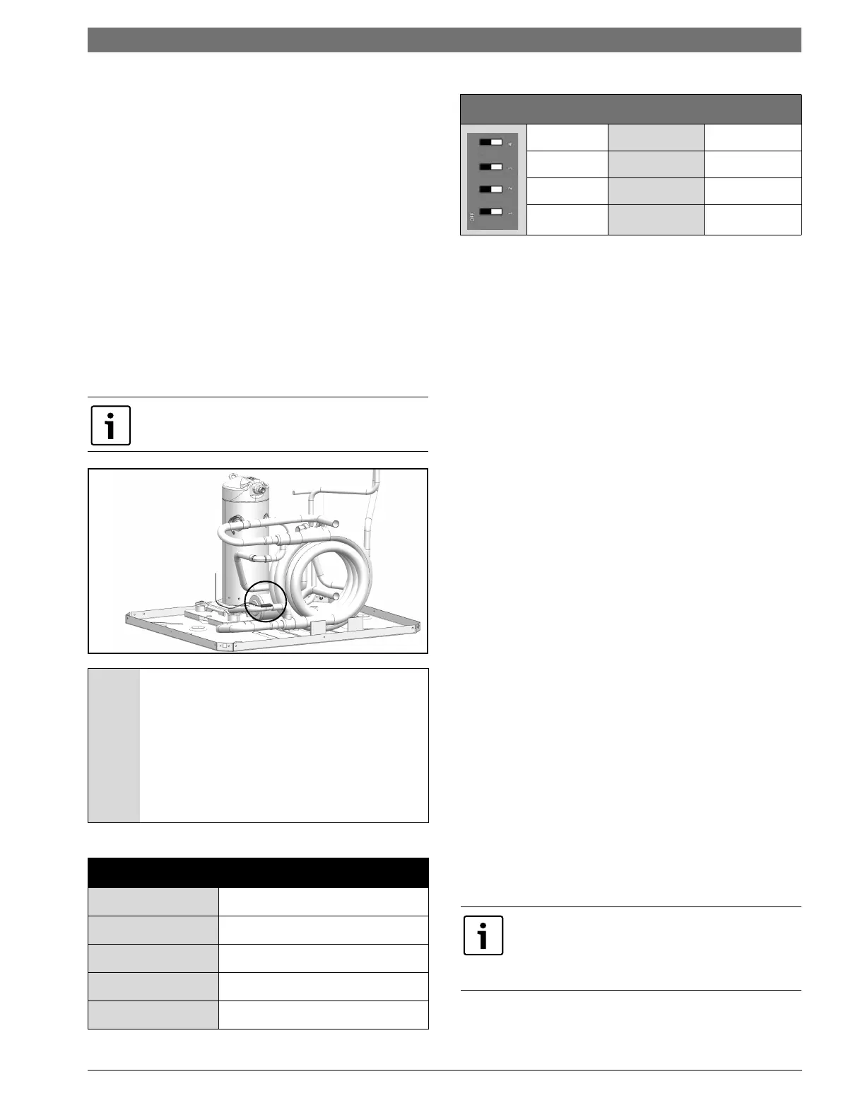
• Water side freeze protection sensor, mounted close
to condensing water coil, monitors refrigerant
temperature between condensing water coil and
thermal expansion valve. If temperature drops
below or remains at freeze limit trip for 30 seconds,
the controller will shut down the compressor and
enter into a soft lockout condition. The default
freeze limit trip is 26°F, however this can be
changed to 15°F by cutting the R30 or Freeze1
resistor located on top of DIP switch SW1 (Refer to
Figure #3, item [3] for resistor location), Refer to
Figure #5 for sensor location
.
Figure # 5
The UPM Board includes the following features:
• ANTI-SHORT CYCLE TIMER: 5 minute delay on
break timer to prevent compressor short cycling.
• RANDOM START: Each controller has an unique
random start delay ranging from 270 to 300 seconds
on initial power up to reduce the chance of multiple
unit simultaneously starting at the same time after
power up or after a power interruption, thus
avoiding creating large electrical spike.
• LOW PRESSURE BYPASS TIMER: If the compressor
is running and the low pressure switch opens, the
controller will keep the compressor on for 120
seconds. After 2 minutes if the low pressure switch
remains open, the controllers will shut down the
compressor and enter a soft lockout. The
compressor will not be energized until the low
pressure switch closes and the anti-short cycle time
delay expires. If the low pressure switch opens 2-4
times in 1 hour, the unit will enter a hard lockout. In
order to exit hard lockout power to the unit would
need to be reset.
• BROWNOUT/SURGE/POWER INTERRUPTION
PROTECTION: The brownout protection in the UPM
board will shut does the compressor if the incoming
power falls below 18 VAC. The compressor will
remain OFF until the voltage is above 18 VAC and
ANTI-SHORT CYCLE TIMER (300 seconds) times out.
The unit will not go into a hard lockout.
• MALFUNCTION OUTPUT: Alarm output is Normally
Open (NO) dry contact. If pulse is selected the alarm
output will be pulsed. The fault output will depend
on the dip switch setting for "ALARM". If it is set to
"CONST", a constant signal will be produced to
indicate a fault has occurred and the unit requires
inspection to determine the type of fault. If it is set
to "PULSE", a pulse signal is produced and a fault
code is detected by a remote device indicating the
fault. See L.E.D Fault Indication below for blink code
explanation. The remote device must have a
malfunction detection capability when the UPM
board is set to "PULSE".
UPM Board Dry Contacts are Normally Open (NO)
NOTICE: If unit is employing a fresh water
system (no anti-freeze protection), it is
extremely important to have the Freeze1
R30 resistor set to 26°F in order to shut
down the unit at the appropriate leaving
water temperature and protect your heat
pump from freezing if a freeze sensor is
included.
UPM Board Factory Default Settings
TEMP
26°F
LOCKOUT
2
RESET
Y
ALARM
PULSE
TEST
NO
UPM DIP SWITCH DEFAULT POSITION
lockout 42
reset
RY
alarm
Cont pulse
test
yes no
If 24 VAC output is needed, R must be wired to
ALR-COM terminal; 24 VAC will be available on
the ALR-OUT terminal when the unit is in the alarm
condition.