10 | Electrical WW & WT Models
WW & WT Models8733943362 (2016/08) Subject to change without prior notice
• DISPLAY OUTPUT: The Display output is a pulse
output connected to the Unit Diagnostic Display
(UDD) and it pulses 24VAC when the unit is in an
lockout alarm condition.
• TEST DIP SWITCH: A test dip switch is provided to
reduce all time delays settings to 10 seconds during
troubleshooting or verification of unit operation.
• FREEZE SENSOR: The default setting for the freeze
limit trip is 26°F (sensor number 1); however this
can be changed to 15°F by cutting the R24 resistor
located on top of the DIP switch SW1. Since freeze
sensor 2 is dedicated to monitor the load side coil it
is recommended to leave the factory default setting
on the board. The UPM controller will constantly
monitor the refrigerant temperature with the sensor
mounted close to the condensing water coil
between the thermal expansion valve and water coil.
If temperature drops below or remains at the freeze
limit trip for 30 seconds, the controller will shut the
compressor down and enter into a soft lockout
condition. Both the status LED and the Alarm
contact will be active. The LED will flash (three (3)
times) the code associated with this alarm
condition. If this alarm occurs 2 times (or 4 if Dip
switch is set to 4) within an hour the UPM controller
will enter into a hard lockout condition. It will
constantly monitor the refrigerant temperature with
the sensor mounted close to the evaporator
between the thermal expansion valve and
evaporator coil as shown in Figure #5. If
temperature drops below or remains at the freeze
limit trip for 30 seconds, the controller will shut the
compressor down and enter into a soft lockout
condition. Both the status LED and the Alarm
contact will be active. The LED will flash (six (6)
times) the code associated with this alarm
condition. If this alarm occurs 2 times (or 4 if Dip
switch is set to 4) within an hour the controller will
enter into a hard lockout condition.
• INTELLIGENT RESET: If a fault condition is initiated,
the 5 minute delay on break time period is initiated
and the unit will restart after these delays expire.
During this period the fault LED will indicate the
cause of the fault. If the fault condition still exists or
occurs 2 or 4 times (depending on 2 or 4 setting for
Lockout dip switch) before 60 minutes, the unit will
go into a hard lockout and requires a manual lockout
reset.
• LOCKOUT RESET: A hard lockout can be reset by
turning the unit thermostat off and then back on
when the “RESET” dip switch is set to “Y” or by
shutting off unit power at the circuit breaker when
the “RESET” dip switch is set to “R”.
Options
Number of factory installed options are available on
select WW and WT Series of Heat Pumps. The following
details the purpose, function and components of each
option.
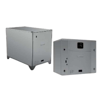
Heat Recovery Package (HRP)
The heat recovery package is a factory installed option
on WW series of heat pumps. The HRP can be used to
heat potable water during unit operation using waste
heat from the compressor discharge gas. In some cases
the HRP can provide most or all of the hot water
requirements for a typical home.
The HRP consists of three major components:
• double wall, vented refrigerant to water heat
exchanger
• circulating pump
• control circuit
The heat exchanger is rated for use with potable water
and is acceptable for use as a domestic water heating
device in most building codes.
The pump circulates water between the domestic hot
water tank and HRP heat exchanger in the Heat Pump.
The control circuit ensures that the HRP only operates
when there is available heat from the compressor and
when the water is within a safe temperature range of
below 140 deg F.
When the heat pump compressor operates, the HRP will
monitor the temperature of the discharge gas from the
compressor. Once discharge gas is hot enough to
provide useful heat to the domestic
water tank, the circulating pump will be enabled,
drawing water from the tank, through the HRP heat
exchanger and then depositing the heated water back
into the tank. If the water temperature reaches 140 deg
F, the circulating pump is disabled to prevent over
heating of the domestic water. The HRP is provided with
an on/off switch in case the end user desires that the
HRP be inactivated (typically during the winter months
when space heating is most important).
NOTICE: Operation of unit in test mode can
lead to accelerated wear and premature
failure of components. The "TEST" switch
must be set back to "NO" after
troubleshooting/servicing.
NOTICE: Freeze sensor will not guard
against the loss of water. Flow switch is
recommended to prevent unit from running
if water flow is lost or reduced.