20 | User Adjustable Settings Chart WW & WT Models
WW & WT Models8733943362 (2016/08) Subject to change without prior notice
USER ADJUSTABLE SETTINGS CHART
SETTING UP THE CONTROLLER
On unit power up the LED display will show the
software version, temperature differential setting with
the ability for the user to change it for ten seconds then
will display “OFF” and then finally will display the
control temperature of the fluid being measured
(entering fluid, leaving fluid, tank,
etc.) The default setting of the differential is 1°F
and can be adjusted from 1 – 10° F at start up.
The differential setting is the differential between set
point temperature and actual on\off temperature of the
machine.
For example:
Cooling set point = 45˚F
Differential = 1˚F
The heat pump will cycle on in cooling at 46˚F. If a
two stage machine, stage 2 will come on at 48˚F or
2˚F degrees above set point and one degree differential.
The unit will shut off at set point.
Heating set point = 120˚F
Differential = 1˚F
Stage one will come on at 119˚F and stage 2 will
come at 117˚F. Both stages will remain running
until set point is achieved. Stage 1 and stage 2 will
cycle on and off according to the lead\lag programmed
interval.
Whenever there is a demand for heating and cooling and
during the first stage of operation the
temperature isn’t changing, then the control will
activate the second stage after a three minute delay from
the first stage activation. This logic will apply when the
control is powered up, on a power interruption, when
the mode function is set to OFF and then back to either
HEAT or COOL and when switching from heating to
cooling or vice versa in the auto changeover mode.
Heating and cooling set points are adjusted by
selecting each mode on the key pad and then using
the up-down arrows to select the set point. Thus, push
cool mode button and use down arrow to 45˚F.
Push heat mode button and use up arrow to 120˚F.
The controller can be set to control heating only,
cooling only, or auto change modes. The mode button is
pushed until the circular LED is lit next to the chosen
control mode.
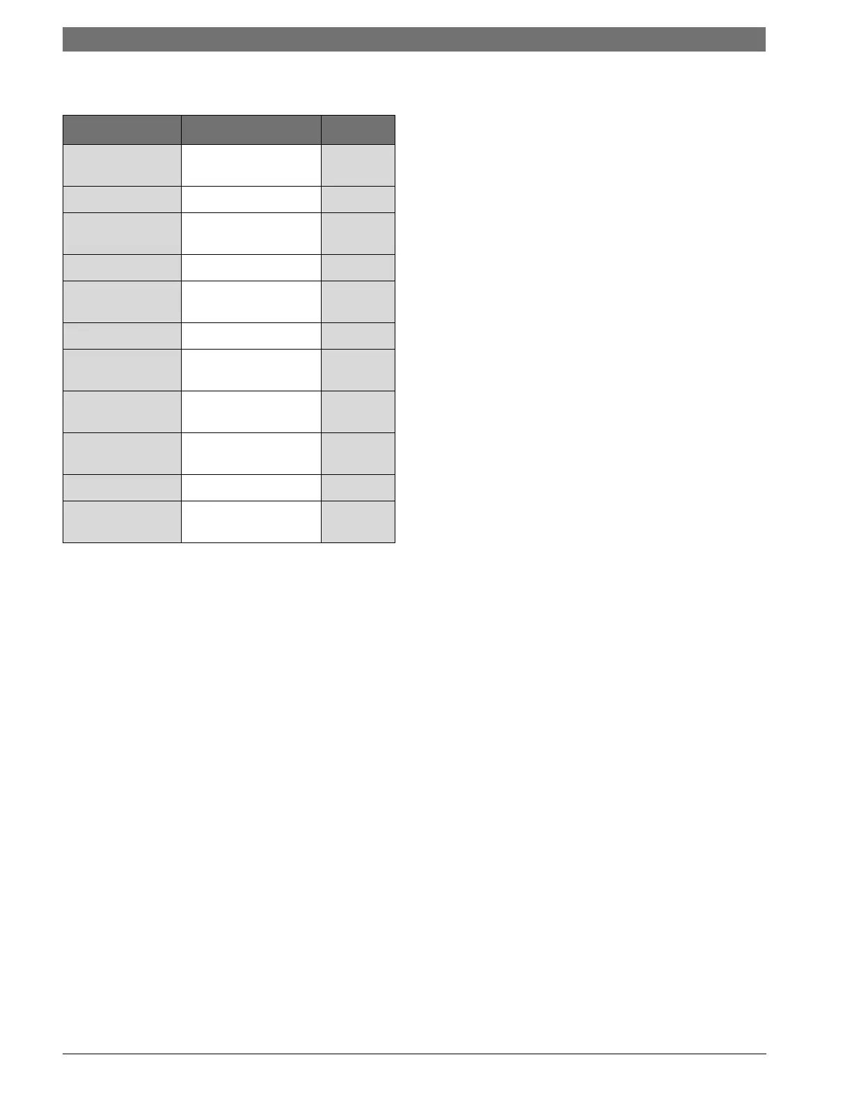
Settings Range Default
TEMP SETTING 40-120° F Heating
and Cooling
DIFFERENTIAL 1-10°F 1°F
MODE Heat, Cool, Auto,
Off
Off
TEMP SCALE F °, C ° F
PUMP MODE Con (continuous),
Cyc (cycle)
Von
DEAD BAND 1-6 ° F 3 ° F
AUTO CHANGE
OVER
55-85 ° F 65 ° F
TEST MODE De (delay), or
Nd (No delay)
De
COMPRESSOR Si (Single),
Du (Dual)
Si
LEAD LAG 0-14 Days 0
MALFUNCTION St (Steady),
Pu (Pulsing)
St