103
LED Functionality
• Power LED (Bi-Colored LED):
GREEN: System functioning properly
FLASHING GREEN: System in standby
AMBER: Thermal fault
RED: Power supply fault (all LED solid red if power supply fault)
• Signal LED (Bi-Colored LED):
GREEN: Signal present in normal level
AMBER: Signal present at a higher level, approaching input clipping
RED: Input signal clip
RED: Power supply fault (all LED solid red if power supply fault)
• Limit LED (Bi-Colored LED):
AMBER: Output is limiting
RED: AMP fault or power supply fault (all LED solid red if power supply fault)
FLASHING RED: Muted
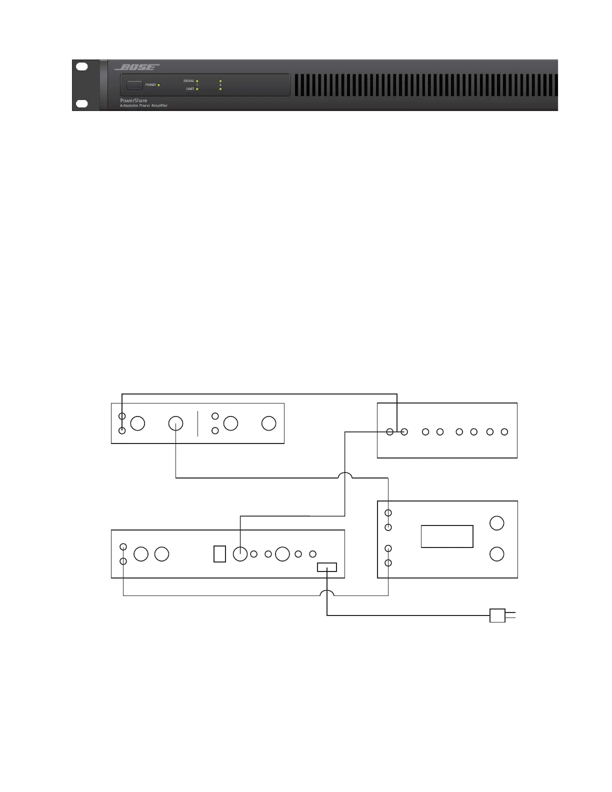
AP AUX-0025
LOAD BOX
UUT (PS602P EXAMPLE)
AP ATS-1
AC MAINS
IN
IN
IN
OUT
OUT
OUT
1. Connect Audio Precision ATS-1 signal generator output to the UUT (unit under test) input as
specified in the test procedures.
2. Connect UUT output to the resistive test load. Use loads specified in the test procedures.
3. Connect load to the AP AUX-0025 digital filter input.
4. Connect the AP AUX-0025 digital filter output to the AP ATS-1 input.
5. Connect the UUT to AC mains.
Test Connections Diagram
 Loading...


