10
Product Description
PowerShare
TM
PS604
The PS604 is a 4-channel installed amplifier that allows its total 600 Watts to be shared asymmetrically
across all four outputs. Independently control the output level, EQ, and low-impedance/high-impedance
(Low-Z/Hi-Z) settings for each output. The PS604 supports built-in loudspeaker EQs for the FreeSpace
®
DS 16, DS 40, DS 100, FS3B, Panaray
®
402 and 802 Series IV, MA12EX, and RoomMatch
®
Utility
RMU105 and RMU108, as well as a Flat setting for FS3 systems. For applications that require more
customization, access the advanced digital loudspeaker processing features using the free web-
downloadable PowerShare Editor Software. The PS604 also supports up to four gangable CC-1
ControlCenter Zone Controllers for remote volume control using CAT-5 cables.
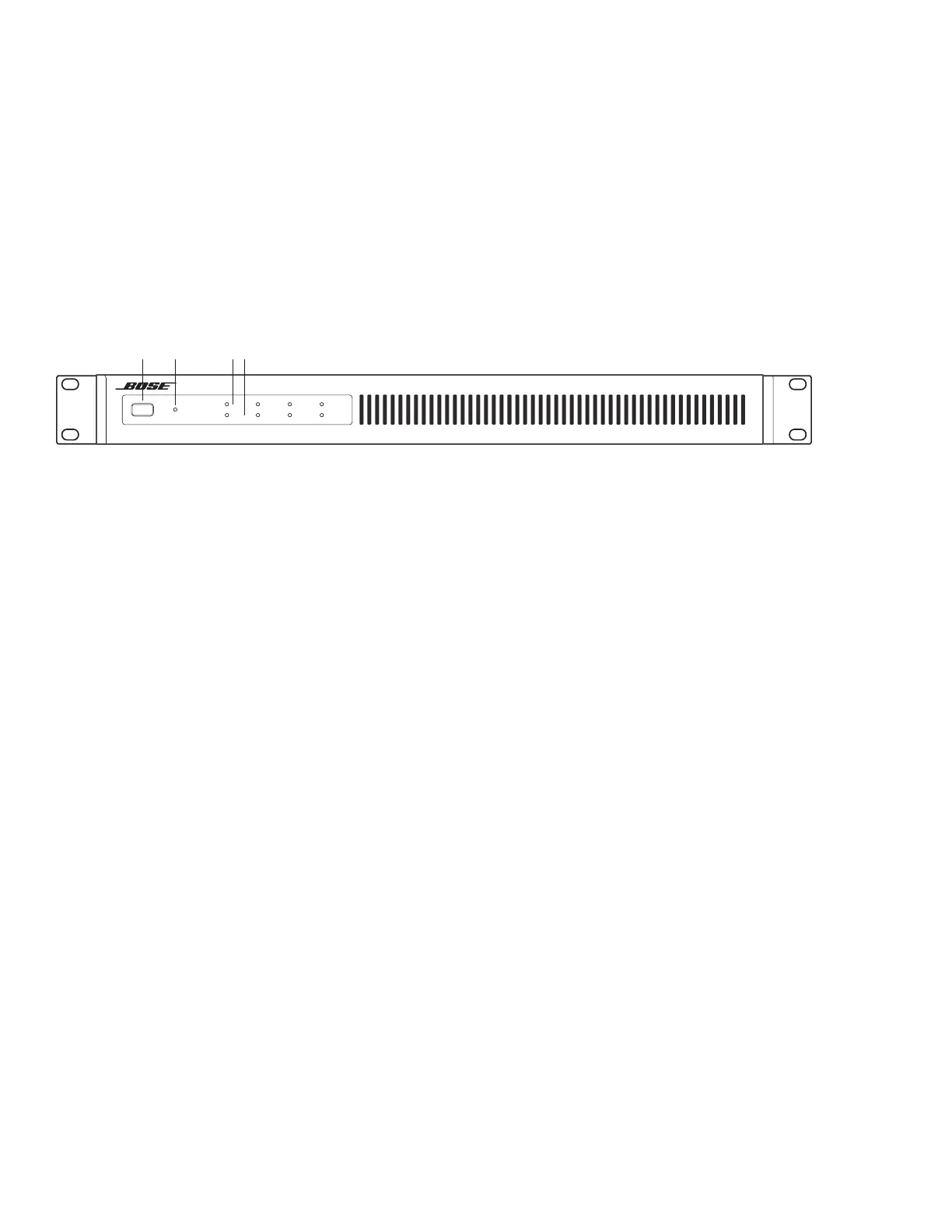
PS604 Front Panel
1. POWER Switch - ON/OFF AC power.
2. POWER LED - Solid green LED indicates the unit is ON. Blinking green LED indicates the unit is in
standby mode. Solid amber LED indicates an over-temperature fault. A solid red LED indicates a power
supply fault.
3. INPUT 1, 2, 3, 4 SIGNAL LED - Each LED operates independently.
• If the SENSITIVITY DIP switch is set to 4 dBu, then the LED is green from -48 dBu to 8.99 dBu,
with a typical input of 4 dBu. LED is amber from 9 dBu to 11.99 dBu. LED goes red, indicating
input clipping, at 12 dBu or over.
• If the SENSITIVITY DIP switch is set to 12 dBu, then the LED is green from -48 dBu to 16.99
dBu, with a typical input of 12 dBu. LED is amber from 17 dBu to 19.99 dBu. LED goes red,
indicating input clipping, at 20 dBu or over
All LEDs go solid red if a power supply fault is detected.
4. OUTPUT 1, 2, 3, 4 LIMIT LED - Each LED operates independently.
• LED is amber when the amplifier is limiting the corresponding output due to exceeding the
specified loudspeaker Vpeak or Vrms limits on an individual channel.
If the sum of the amplifier outputs exceeds 600 Watts peak, then the amplifier will limit all outputs
equally, and all LEDs will show limiting simultaneously. This is because the amplifier is also
measuring and limiting total output power, in addition to individual channel output power. The
amplifier is capable of delivering one-third (1/3) power continuously, 200 Watts peak.
• Each OUTPUT LIMIT LED will go solid red if there is an EHF fault on the corresponding output.
LED 1 & 2 will go solid red when the outputs are muted due to an amplifier one fault. LED 3 & 4
will go solid red when the outputs are muted due to an amplifier two fault.
• All four LEDs will go solid red when all outputs are muted due to an amplifier fault, or if there is
a power supply fault
• All four LEDs will blink red when all outputs are muted from the rear panel mute connector.
Adaptable Power Amplier
LIMIT
SIGNAL
12 3 4
Power Share
PS604
POWER
12 34
 Loading...


