15
Bowflex
®
TreadClimber
®
Service Manual
MECHANICAL SERVICE GUIDE
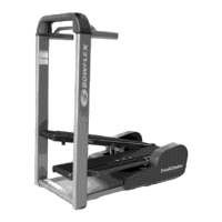
Figure 1:
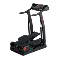
Figure 2:
6.0 - REPLACEMENT OF SPEED SENSOR
Tools Needed:
• Phillips Screwdriver
NOTE: If using a powered driver, it must be on the
“LOW TORQUE” setting, otherwise it will
strip screws.
6-1
Unplug machine from wall outlet.
6-2 Wait 5-minutes after unplugging machine to
ensure there is no residual power.
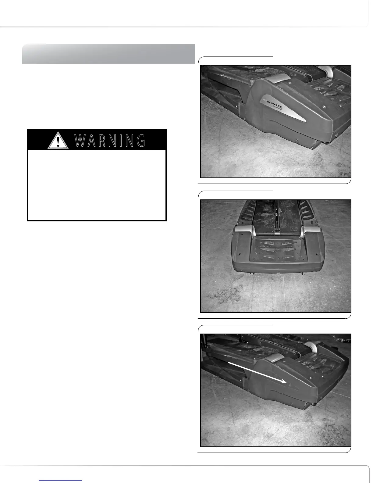
6-3 Remove rear step plastic cover (8 screws), right
and left rear base plastic covers (3 screws each),
and rear base plastic cover (5 screws). See
Figures 1 & 2.
NOTE: One screw each on the right and left side
base plastic is behind the decal
(see Figure 3).
6-4 Remove rear step cover (4 screws). See Figure 4.
6-5 Looking at machine from left side, locate black
wire connected to hole in left rear drive bracket
(wire is approximately 3 3/4 inches long and is
located below left rear roller) see Figure 5 & 6.
6-6 Disconnect white cable connector from speed
sensor wire that is attached to long black wire
(see Figure 6).
AS LONG AS THE TREADCLIMBER
®
FITNESS
MACHINE IS PLUGGED INTO A POWERED OUTLET
AND THE POWER SWITCH IS ON, THE UNIT IS
RECEIVING POWER, EVEN IF THE DISPLAY IS
TURNED OFF. ALWAYS UNPLUG THE POWER CORD
FROM THE OUTLET AND WAIT 5-MINUTES BEFORE
PERFORMING REPAIRS OR MAINTENANCE.
7 ! 2 . ) . '
! 4 4 % . 4 ) / .
$ ! . ' % 2
)--%$)!4%!#4)/.2%15)2%$
# ! 5 4 ) / .
Figure 3:
One screw behind decal.