BPW-EA-AS 37772001de Page 17
English
Assembly 4
Assembling the AirSave Control Box 4.3
[4] Insert the AirSave Control Box into the bore holes
with the fi xing screws.
[5] Screw on the lock nuts (SW 13) with washers and
tighten to a tightening torque of 25 Nm.
4.3 Assembling the AirSave Control Box
Installation and repair guide!
When drilling the fastening holes, pay
attention to power and pneumatic lines
and to supporting parts.
To connect to the vehicle cabling, use
only round cables with a cross-section
Ø 6 – 10 mm to guarantee the sealing of
the PG11 screwed joint.
The AirSave Control Box should be
assembled in a protected and easily
accessible area in the vicinity of the
pneumatic fi ttings.
The switch box cover plate must be remo-
vable for adjustment work and must not be
locked.
There must be a clearance of min. 50 mm
in front of the vent.
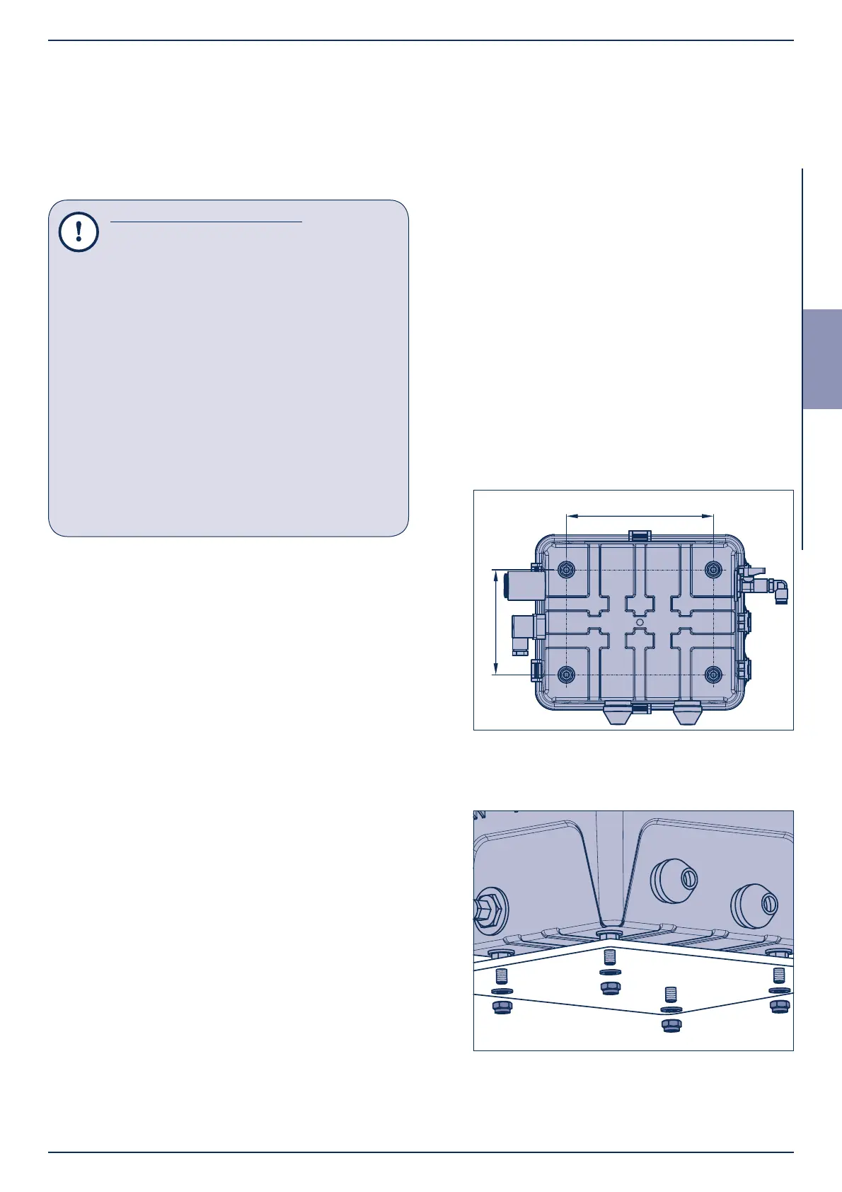
[1] Hold the AirSave Control Box (842) in the required
installation position.
[2] Mark positions for the fi xing holes.
[3] Drill Ø 9 mm holes and deburr slightly.
Figure 8
Figure 7