EasyManua.ls Logo

BRANNSTROM BilgMon488 User Manual

BRANNSTROM BilgMon488
38 pages
To Next Page IconTo Next Page
Page #1 background imageLoading...
Page #1 background image
BilgMon488 Instruction Manual vAD 1(38)
BRANNSTROM SWEDEN AB
www.brannstrom.se
INSTRUCTION MANUAL
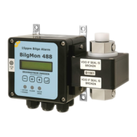
BilgMon488
15 ppm Bilge Alarm

Table of Contents

Questions and Answers:

BRANNSTROM BilgMon488 Specifications

General IconGeneral
BrandBRANNSTROM
ModelBilgMon488
CategorySecurity System
LanguageEnglish

Summary

Table of Validity

Introduction

Construction

Operation

Caution

Technical Specifications

General Specifications

Covers measurement range, accuracy, alarms, interface, and environment.

115/230 V AC Model Specifications

Details electrical input/output for the 115/230V AC version.

24 V AC/DC Model Specifications

Details electrical input/output for the 24V AC/DC version.

Installation Procedures

Mechanical Installation

Provides dimensions and mounting screw details for the unit.

Tube Arrangement Alternatives

Illustrates two methods for connecting tubing to the unit.

Electrical Installation Overview

Details PCB layouts and connections for different voltage models.

Fresh Water Flushing Valve Installation

Explains how to install the cleaning solenoid valve.

115/230 VAC Electrical Connections

Wiring diagram for the 115/230 VAC model.

24V AC/DC Electrical Connections

Wiring diagram for the 24V AC/DC model.

Calibration Check

Calibration Schedule and Expiry

Addresses maintenance schedule for calibration certificates and their expiry dates.

Calibration Check Requirements

Outlines when and how to perform on-site calibration checks as required.

Sensor Unit Replacement

Step-by-step guide for removing and installing the SENSOR unit, including Master unit preparations.

Operating Instructions

Startup Sequence and Main Menu

Describes the initial power-up sequence and the main display.

LED Indicators and Status

Explains the meaning of front panel LEDs for operational status.

Menu System Navigation

Overview of the unit's menu structure and navigation.

Contrast and Simulation Settings

Adjusting display contrast and simulating unit behavior.

Alarm and Stopping Device Control

Forcing device activation and acknowledging alarms.

Information Menu

Accessing MASTER and SENSOR unit details and software versions.

Log Menu and Data Access

Navigating and retrieving logged data from the unit.

Cleaning and Test Functions

Procedures for cleaning the sensor and performing calibration checks.

Settings Configuration

Configuring valve, alarm, autoflush, and clock settings.

Current Output Settings

Configuring current output modes and calibration.

Display and Standby Settings

Customizing PPM display format and standby notification.

Testing Procedures

Automatic Stopping Device Test

Procedures for testing the automatic stopping device functionality.

Response Test Methods

Methods to verify sensor response and alarm activation.

Calibration Check Details

Information on performing calibration checks and limitations.

Log Entries

Maintenance

Real Time Clock (RTC)

Local Time Settings

Adjusting the displayed time and date, affecting main menu and log entries as an offset to RTC.

Battery Replacement Procedure

Step-by-step guide for replacing the RTC backup battery (CR1225) in the master unit lid.

RTC Malfunction Handling

Describes error messages for RTC stopping and outlines recovery steps via the RTC recovery menu.

Set UTC Time

Procedure for setting the correct UTC time and date after an RTC malfunction or battery replacement.

Log Data Download via USB

Running the Log Receiver Software

Instructions for starting the PC software for log download.

Installing the VCP Driver

Guide for installing the necessary USB driver for PC connection.

Download Procedure Steps

Detailed steps to transfer log data from the unit to the PC.

Spare Parts List

Troubleshooting