BilgMon488 Instruction Manual vAD 10(38)
BRANNSTROM SWEDEN AB
www.brannstrom.se
8.3 ELECTRICAL
8.3.1 General installation
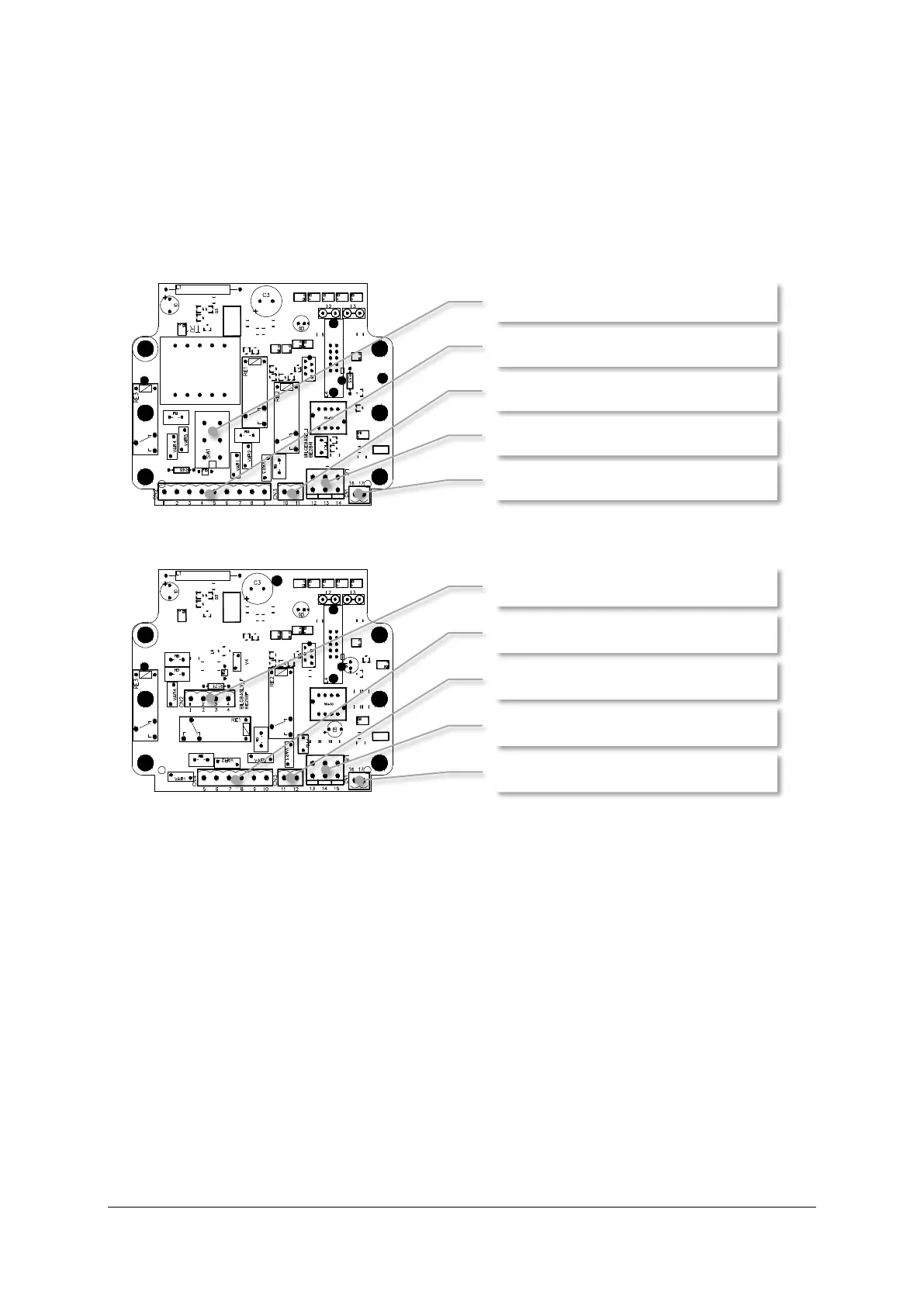
Bilgmon488 is manufactured in two base models, 115/230 VAC and 24 V AC/DC. The main difference
between these two models is the base PCB of the MASTER unit.
Illustration 4: Base PCB of 115/230 VAC MASTER unit.
Illustration 5: Base PCB of 24 V AC/DC MASTER unit.
When installing the 115/230 VAC model be sure to put the voltage selection switch (SW1, Illustration
4) in the correct position (marked 115 resp. 230).
Terminals 12-14 (L8, Illustration 4) resp. 13-15 (L8, Illustration 5) are coupled and can be used for
routing of external protective earth connections.
See sections 8.3.3 and 8.3.4 for detailed information of electrical connections.
SW1: Voltage selection switch (115/230)


 To Next Page