© 2022 Brivo Systems LLC. All rights reserved. PUB-Brivo ACS6100 Installation Manual
25
Brivo ACS6100 Installation Manual
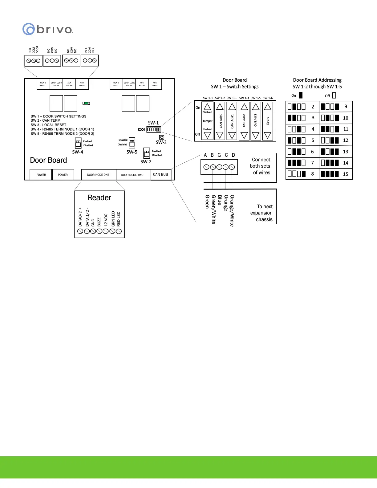
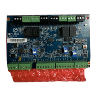
Figure 18 - Wire DOOR BOARD
NOTE: Output Ratings for the B-ACS6100-DB Door Board
• Two (2) reader ports, 12V, 500mA for each reader.
• Four (4) relays on the Door Board. The ratings are 28VDC, 3A each.
1. Wire the REX & DOOR terminal block.
a) Connect the Normally Open (NO) contacts of the REX device to the REX and COM terminals.
• When this switch closes, it initiates a Request-to-Exit (REX) program sequence, as
dened by the appropriate application, including the option to activate the door or
other relays, re the door strike, and suppress any “Door Forced” messages.
b) Connect the Normally Closed (NC) contacts of the Door Sensor to the COM and CONTACT
terminals.
• In this context, an NC switch is considered closed when the door is closed (magnet is
present), and open when the door is open (no magnet is present).
• When the switch is open, the control panel interprets this input as a “Door Open”
condition. When the switch is closed, the control panel interprets this input as a
“Door Closed” condition.
• This circuit provides door status information (open/closed) to the control panel so
the application can take appropriate action locally, or send email notications if
necessary.
2. Wire the DOOR LOCK RELAY terminal block.
a) Connect the door latch to the COM terminal and either the NO or NC terminal.
b) The DOOR LOCK RELAY provides both NO (Normally Open) and NC (Normally Closed)