8 Brocade FastIron X Series Chassis Hardware Installation Guide
53-1001723-02
Hardware features
1
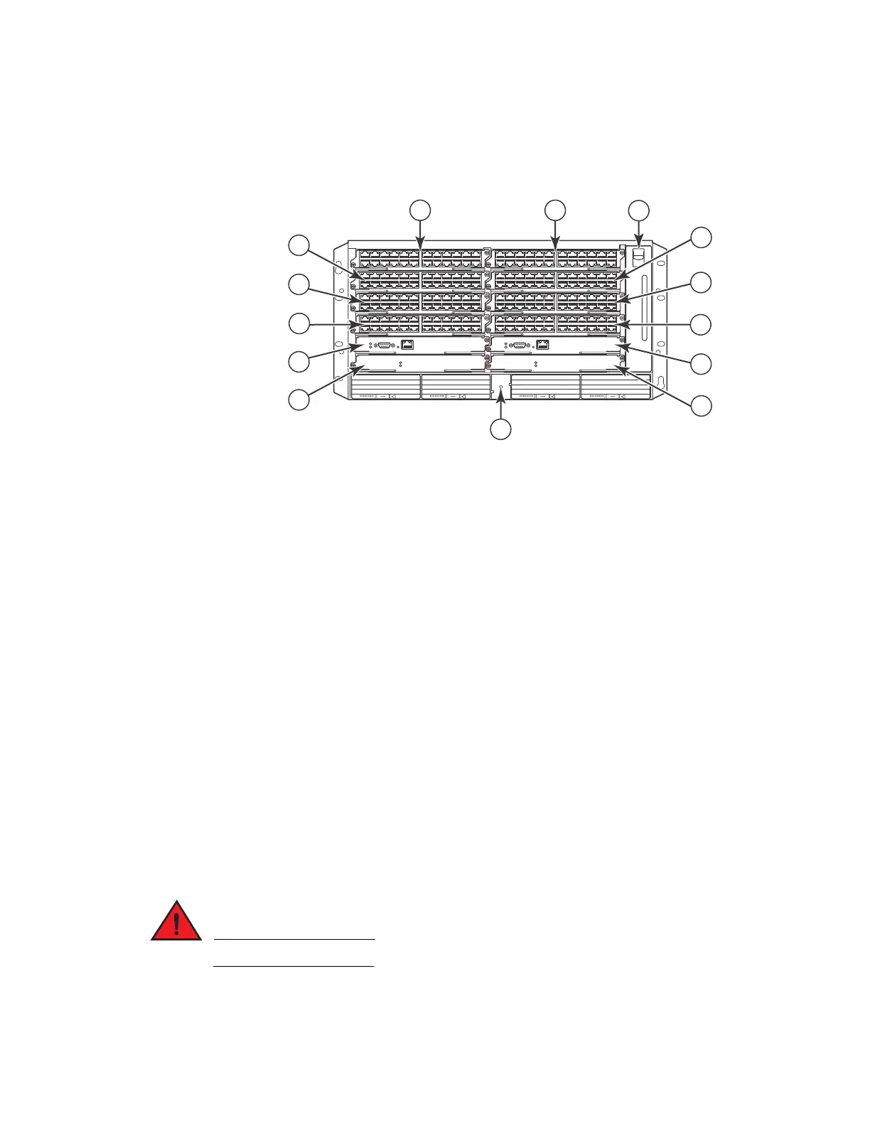
Figure 4 shows the FSX 800 Chassis and the slots into which you can install the various modules
and power supplies.
FIGURE 4 FSX 800 chassis slots
Figure 4 also shows an electrostatic discharge (ESD) connector, into which you can plug an ESD
wrist strap to ground yourself while handling and installing modules.
For safety reasons, the ESD wrist strap should contain a series 1 meg ohm resistor.
1Slot 1
2Slot 2
3Slot 3
4Slot 4
5Slot 5
6Slot 6
7Slot 7
8Slot 8
9Slot 9
10 Slot 10
11 Switch Fabric Slot 1
12 Switch Fabric Slot 2
13 Fan tray
14 ESD connector
AC OKDC OK ALM
EJECT SYS
AC OKDC OK ALM
EJECT SYS
AC OKDC OK ALM
EJECT POE
AC OKDC OK ALM
EJECT POE
F1
424C
F1
424C
F1
424C
F1
424C
F1
424C
F1
424C
F1
424C
F1
424C
Pwr
Active
Pwr
Console
Ethernet
10/100/1000
Active
Pwr
Active
Pwr
Console
Ethernet
10/100/1000
Active
7
3
5
9
11
8
4
6
10
12
1
14
2
13

 Loading...