Brocade FastIron X Series Chassis Hardware Installation Guide 47
53-1001723-02
Preparing the installation site
2
Preparing the installation site
Cabling infrastructure
Ensure that the proper cabling is installed in the site. For information on cabling, refer to the
following sections in this guide:
• “Attaching a management station” on page 56
• “Connecting network devices” on page 76
• “Cable specifications” on page 168
Installation location
Before installing the device, plan its location and orientation relative to other devices and
equipment. Allow at least 3 inches of space at the front of the device for the fiber-optic and power
cabling. Also, allow a minimum of 3 inches of space between the sides and the back of the device
and walls or other obstructions.
Removing extra shipment screws (FSX and
FSX 800
only)
The FSX and FSX 800 ship with two extra screws installed in the right side of the chassis. These
screws secure the fan tray, protecting it from damage during shipment. You must remove these
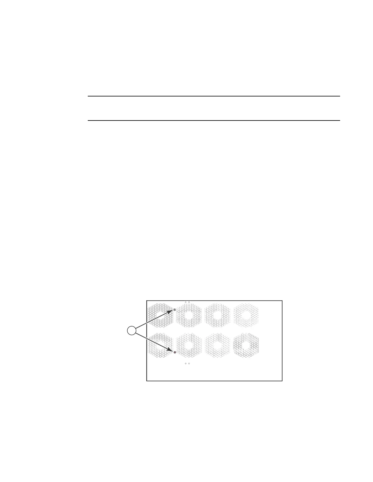
screws before installing the chassis. Figure 27 shows the location of the screws.
To perform this task, you need a #2 Phillips-head screwdriver.
FIGURE 27 Removing the extra screws used for shipment
1 Shipping screws
1
Chassis front Chassis rear

 Loading...