66 Brocade FastIron X Series Chassis Hardware Installation Guide
53-1001723-02
Verifying proper operation
2
If a problem persists after taking action described in this table, contact Brocade’s technical
support.
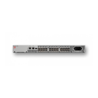
Displaying the module status
After you have attached a PC or terminal to the management module’s Console port or Ethernet
port and the Brocade device has initialized successfully, press Enter to display the following CLI
prompt in the terminal emulation window.
FastIron>
If you do not see this prompt, complete the following steps.
1. Make sure the cable is securely connected to your PC or terminal and the Console port or
Ethernet port.
2. Check the settings in your terminal emulation program. In addition to the session settings
listed in “Attaching a PC or terminal to the console port or 10/100/1000 copper port” on
page 57, make sure the terminal emulation session is running on the same serial port you
attached to the Console port.
If you view the prompt FastIron> or similar, you are connected to the system and can display the
status of the modules using the CLI. Enter the show module command at any CLI level.
The following shows the output of the show module command when entered on the FSX.
DC OUT ON – Green (steady) The power supply is
supplying DC output power
to the chassis
OFF The power supply is not
supplying DC output power to
the chassis.
If this occurs and the AC OK (AC
power supply) or DC IN (DC
power supply) LED is Green,
then there is a problem with the
power supply and it must be
replaced.
ALM OFF No alarms present and the
power supply is in normal
operating condition.
Amber There is an alarm present and
the power supply is
malfunctioning.
Verify the AC or DC input and DC
output voltages.
TABLE 17 Desired and abnormal LED states after system power on (Continued)
LED Desired State Meaning Abnormal
State
Meaning or Action
FastIron# show module
Module Status Ports Starting MAC
S1: SX-424C 24-port Gig Copper Module OK 24 00e0.5200.0100
S2: SX-424C 24-port Gig Copper Module OK 24 00e0.5200.0120
S3:
S4: SX-424C 24-port Gig Copper Module OK 24 00e0.5200.0160
S5: SX-424C 24-port Gig Copper Module OK 24 00e0.5200.0180
S6: SX-424C 24-port Gig Copper Module OK 24 00e0.5200.01a0
S7:
S8:
S9: SX-12GM-4 12-port Management Module OK 12 02e0.5200.0120

 Loading...