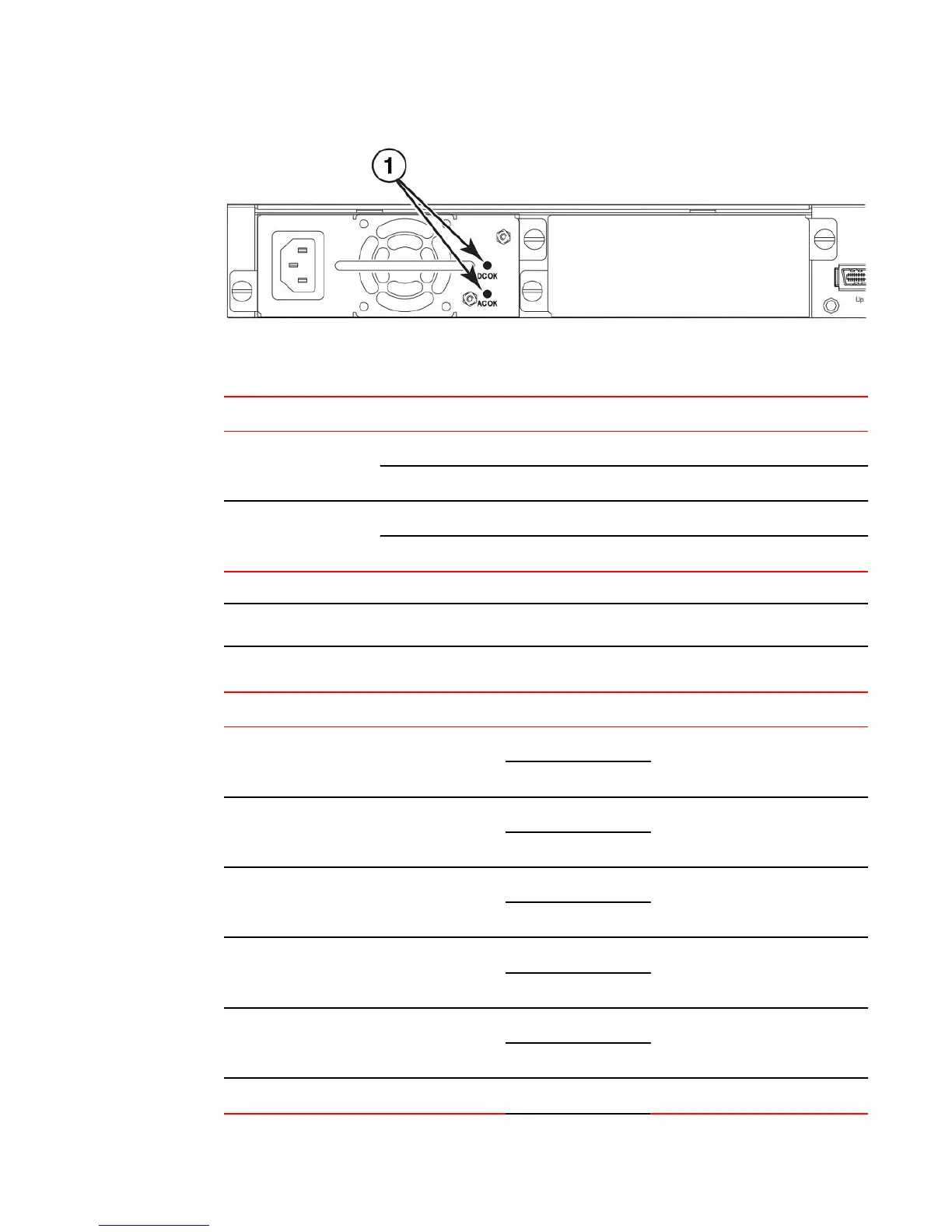
1. Power status LEDs
Power status LEDs TABLE 14
LED Condition Status
DC OK Green DC output ok
Red DC output fail
AC OK Green AC input ok
Off AC input fail
NOTE
Both "AC OK" and "DC OK" LEDs must be green for the device to function normally.
Switch status for two installed power supply units TABLE 15
State LED PSU1 PSU2 Switch Status Redundancy
Four Green PSU LEDs AC OK Green Green Running Yes
DC OK Green Green
Single Red ‘DC OK’ LED AC OK Green Green Running No
DC OK Green Red
Both ‘DC OK’ LEDs Red AC OK Green Green Failure No
DC OK Red Red
One PSU with both ‘AC OK’ ‘DC OK’ LEDs Off AC OK Green Off Running No
DC OK Green Off
‘DC OK’ LEDs Red and Off AC OK Green Off Failure No
DC OK Red Off
All ‘AC OK’ LEDs Off AC OK Off Off Power Off or Failure No
Product Overview
Brocade FCX Series Hardware Installation Guide 31
53-1002977-01

 Loading...


