TABLE 4 Network connection-related LED states (continued)
LED Desired state Meaning Abnormal state Meaning or action
port or a dierent
cable.
If a problem persists after taking these actions, contact Brocade Technical Support.
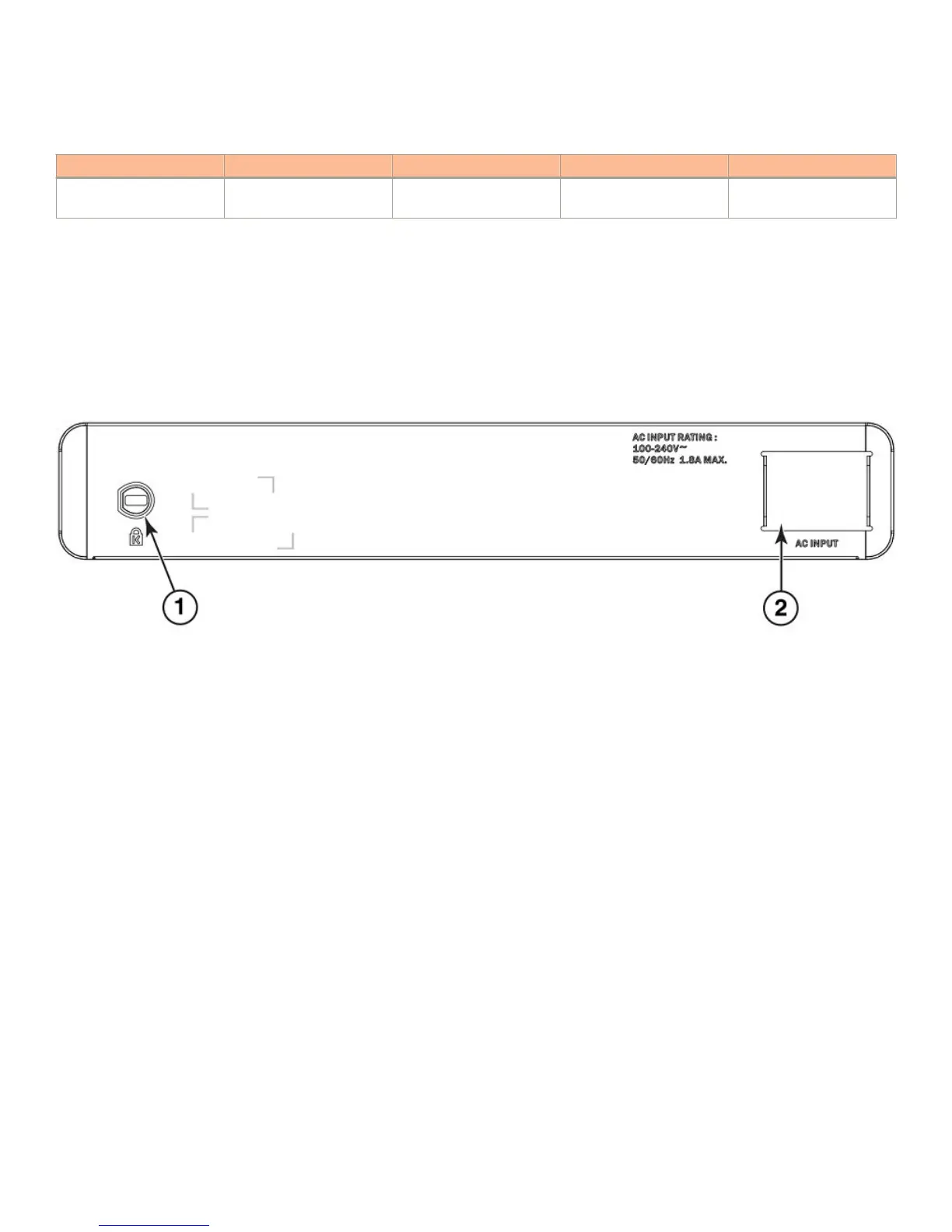
Power supplies
An ICX 6430-C device has one standard power supply receptacle on the rear panel of the device for the AC power cord.
FIGURE 4 ICX 6430-C AC power connection
1. Kensington lock hole
2. AC power supply socket
Power supply usage
The maximum power capacity of the ICX 6430-C12 device is 100W. 23W drawn from the AC line power supply input (of the total
100W capacity of the device) are necessary to power the ICX 6430-C12 device. PoE/PoE+ power capacity and output capability is
68W.
Power supplies
Brocade ICX 6430-C Compact Switch Hardware Installation Guide
18 Part Number: 53-1003618-02
 Loading...