3. INSTALLATION
BAS-311HN, BAS-326H
10
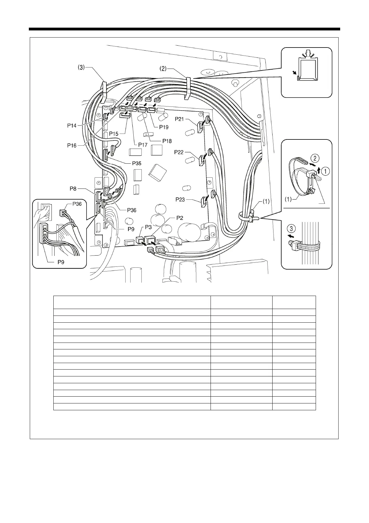
NOTE: Route the X, Y and work clamp pulse motor harnesses so that they do not touch the power supply P.C. board at the
bottom of the control box.
Connectors
Connection location on
main P. C. board
Cord clamps /
cable ties
X pulse motor encoder [5-pin] White P17 (X-ENC) (2)
Y pulse motor encoder [5-pin] Blue P18 (Y-ENC) (2)
Intermittent presser foot pulse motor encoder [5-pin] Black P19 (P-ENC) (2)
Machine head switch [3-pin] P14 (HEAD-SW) (2)
Conversion harness (two-pedal foot switch) [7-pin] White P15 (PEDAL) (2)
Machine head memory [6-pin] P16 (HEAD-M) (2)
Thread trimmer solenoid [6-pin] P2 (SOL1) (1)
Digital tension solenoid / Tension release solenoid [4-pin] P3 (SOL2) (1)
X pulse motor [4-pin] White P21 (XPM) (1)
Y pulse motor [4-pin] Blue P22 (YPM) (1)
Work clamp pulse motor [4-pin] Black P23 (PPM) (1)
Home position sensor [12-pin] White P8 (SENSOR1) (2) (3)
STOP switch [6-pin] White P9 (HEAD) (2) (3)
Valve harness [12-pin] (pneumatic work clamp specifications) P35 (EX-OUT1) (2) (3)
Upper thread breakage detector [2-pin] White P36, P9(HEAD) (2) (3)
3542B
< Main P. C. board >
Lock the cord
clamp securely.
<Removal>
Press the tab.
<Securing>
 Loading...