BCU05 Version 006 BRUKER 11 (41)
Installation
2. Place the cooling unit at approximately 2 m from the magnet. Open the unit
and carefully unroll the heat exchanger.
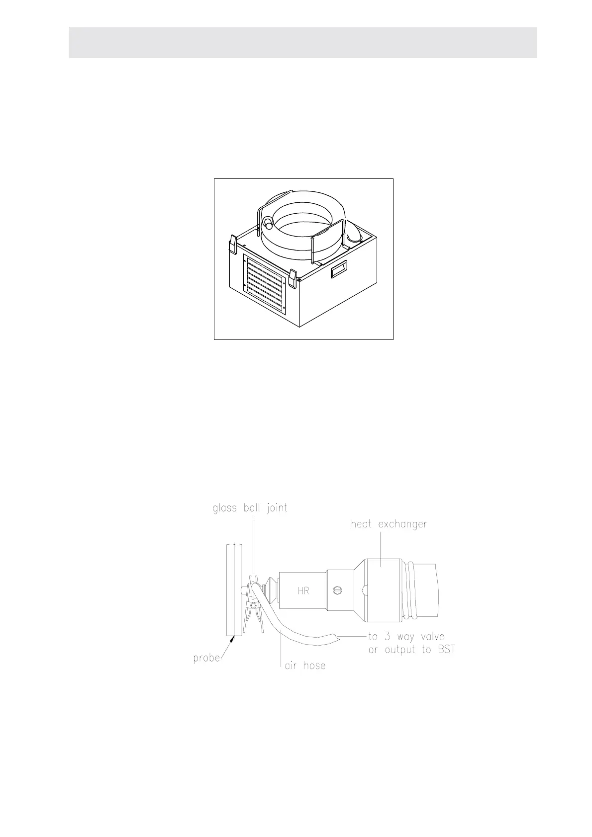
Figure 1.2. Heat exchanger (M151460A)
1. Put some vacuum grease on glass ball-joint before clamping the heat ex-
changer. Take care to keep the right distance between the probe glass ball-
joint and the support clamp. Connect the air hose to the three way valve ex-
haust.
Figure 1.3. Glass ball joint (M151454B)
2. Take the heat exchanger support stand and position it between the magnet
and the unit. Adjust the height.

 Loading...


