20 (41) BRUKER BCU05 Version 006
BCU05 HR-MAS applications
Identification of parts 2.2
• Mains breaker with power control light P/N 75370
• Heat exchanger
• Heat exchanger support stand P/N W1208509
Following parts are supplied :
• BCU05 cooling unit with heat exchanger
• Heat exchanger support stand
• Plastic input air hoses
• Two half shells for heater exchanger clamping,
see "
Mounting the support clamp" on page 10
Installation 2.3
See Installation BCU05 HR "Installation" on page 10
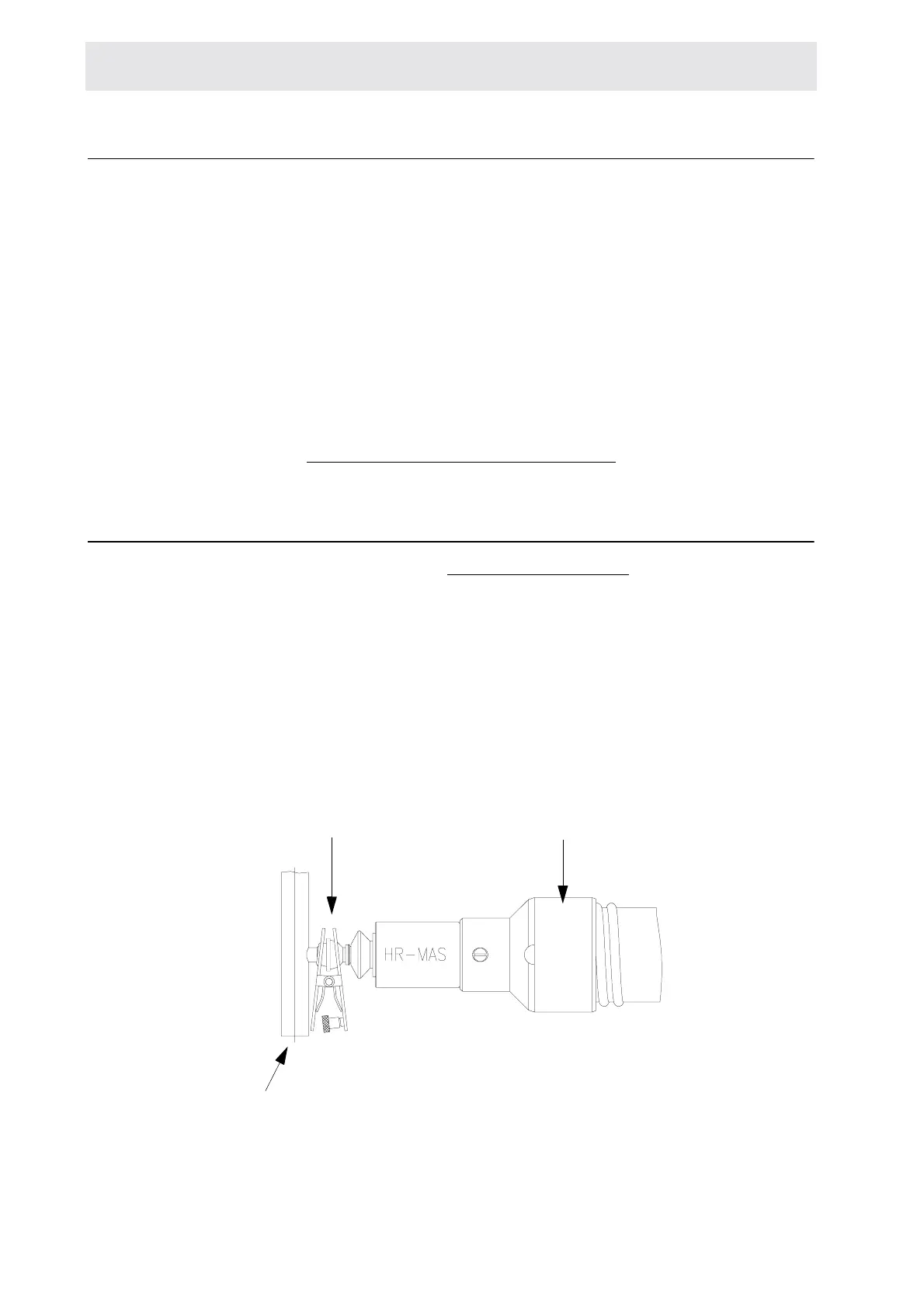
Put some vacuum grease on glass ball-joint before clamping the heat exchanger.
Take care to keep the right distance between the probe glass ball-joint and the
support clamp. Connect the air hoses to the three Mas Remote Control unit !
Figure 2.1. Glass ball joint (W4M123713A)
1. Take the heat exchanger support stand and position it between the magnet
and the unit. Adjust the height.
heat exchanger
glass ball joint
probe

 Loading...


