BCU05 Version 006 BRUKER 13 (41)
Installation
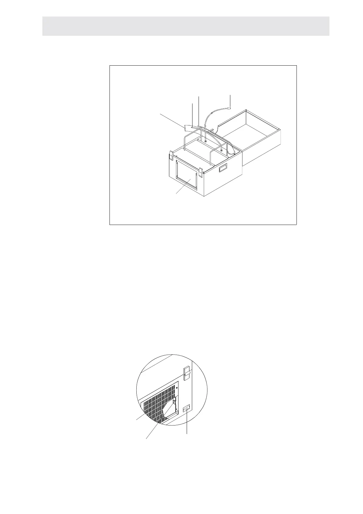
Figure 1.5. BCU05 connections
4. Connect the nitrogen (or dry air) input from the BVT.
5. Set the air flow rate to approximately 500 l/h at the BVT. Check that the sample
spinning is not affected. If yes, decrease the air flow rate.
Note: Please install the unit only on a hard floor.
6. If the BCU05 is controlled by a BVT3000/3300, connect the BVT plug to the
connector called «BCU05» located on the BVT's front panel.
7. In stand alone mode, don't connect the BVT plug and close the switch located
behind the rear grill.
Figure 1.6. Rear grill
filter
heat exchanger
dried air or N2 in
mains
BVT connector
switch
serial number plate
rear grill
 Loading...


