32
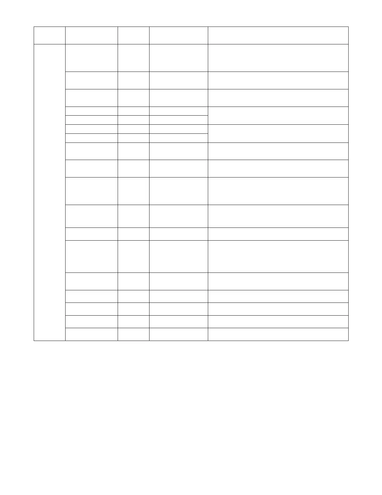
Table 12 -- Menu Structure* (cont)
Menu Parameter
Parameter
Default
Value
Parameter
Range and Increment
[
EXPANDED P ARAMETER NAME
Notes
ALARMS(#)
Alarmsdisplayonlywhentheyareactive.Themenutitle
“ALARM S(#)” includes the number of active alarm s in parenth esis ( ).
Wh en using S---Bus sensors , “SYL K ” will app ea r on the screen, an d
wh en usi n g 20k OA tem per atur e sens or s, “SENS T” will app ea r on
the screen .
MA T SENS ERR n/a n/a SUPPLY AIR TEMP ER ATURE SENSOR ERROR
Supply air sensor has failed or become disconnected - -- check wiring
then replace sensor if the alarm continues
CO2 SENS ERR n/a n/a CO
2
SENSOR ERROR
CO
2
se nsor has fai le d , gone out of range or beco me disconnected ---
check wi ring then replac e se ns o r if the alarm cont inues
OA SYLK T ERR n/a n/a
OUTSIDE AIR S -- -BUS SENSOR ERROR
Outs id e air enthalpy sensor has failed or become dis connected --- check
wi ring then rep lac e sens or if the alarm cont inues
OA SYLK H ERR n/a n/a
RA SYLK T ERR n/a n/a
RETURN AIR S ---BUS SENSOR ERROR
Return air enthalpy sensor has failed or become dis connected --- check
wi ring then rep lac e sens or if the alarm cont inues
RA SYLK H ERR n/a n/a
DA SYLK T ERR n/a n/a DISCHARGE AIR S ---BUS SENSOR ERROR
Discharg e air sens or has failed or become disconnec t e d --- chec k wiring
then replace sensor if the alarm continues
OA SENS T ERR n/a n/a OUTSIDE AIR TEMPERATURE SENSOR ERROR
Outs id e air temperature sensor has fai led or become disc onnected ---
check wi ring then replac e se ns o r if the alarm cont inues
ACT ERROR n/a n/a ACTUATOR ERROR
Act uator has failed or become dis connected --- check for stall, over
voltage, under voltage and actuator count. Replace actuator if damper is
moveable and supply voltage is between 21.6 V and
26. 4 V. Check actuator count on STATUS menu.
FREEZE ALARM n/a n/a Check if outdoor temperature is below the LOW T emp Loc kout on
se t p o i nt menu. Check if Mixed air temperature on ST ATUS menu is
be low the Lo Set p o int on Ad v anced set up menu. When cond itio ns are
back in normal range then the alarm will go away.
SHUTDOWN ACTIVE n/a n/a AUX2INisprogrammedforSHUTDOWNand24Vhasbeenappliedto
AUX 2IN terminal
DMP CAL RUNNING n/a n/a DAMPER CALIBRATION ROUTINE RUNNING
If DCV Auto enable has been programmed, when the W7220 is
com p le t ing a calibratio n on the dampers, thi s alarm will di s p la y. W a i t until
the calibration is completed and the alarm will go away. Must have OA,
MA and RA se ns o rs for DCV cali b ra t ion; set up is in the Ad v anced set up
menu.
DA SENS ALM n/a n/a DISCHARGEAIRTEMPERATURESENSORALARM
Discharge air temp e ra t ure is out of the rang e se t in the ADVAN CED
SETUP Menu. Check the temperature of the di scharg e air.
SYS ALARM n/a n/a When AUX1---O is set to SYS and there is any alarm (e.g., fai led sensors,
etc.), the A UX1---O terminal has 24 Vac out.
ACT UNDER V n/a n/a ACTUA TOR VOLTAGE LOW
Voltag e received at actuator is below expected range
ACT OVER V n/a n/a ACTUATOR VOLTAGE HIGH
Voltag e received at actuator is above expected rang e
ACT STALLED n/a n/a ACTUA TOR STALLED
Act uator stopped before reaching commanded posi t ion
*
Table 12 illustrates the complete hierarchy. Your menu parameters may be different depending on your configuration.
For example if you do not have a DCV (CO
2
) sensor, then none of the DCV parameters appear.
[
When values are displayed, pressing and holding the Y or B button causes the display to au tomatically increment.
**
n/a = not applicable
[[
ERV Operati on: When in Cooling mode AND the conditions are NOT OK for economizing --- the ERV terminal will be energized.
In the Heating mode the ERV terminal will be energized when the OA is below the ERV OAT setpoint in the setpoint menu.
***
When used with communicating actuator the damper out is reported in XX .X% open verses XX.X Vdc.
[[[
After 10 minutes without a command or mode change, the controller will change to normal operation.
Menu Notes
1 S T A T U S --- > O C C U P I E D – The factory-standard Occupancy signal originates with a thermostat or other controller call for indoor fan operation at CTB ter-
minal G. This signal passes through the Central Terminal Board’s OCCUPIED ju mper J MP1 to the ECONO connector and to the W7220’s OCC input termin-
al. An external timeclock or relay is required to implement an Occupancy schedule on the economizer damper position.
2 STATUS -> MA TEMP, SETPOINTS -> MAT SET – The W7220 menu parameters and labels include designations MA, MAT and Mixed Air for the economizer
cooling control sensor. On these rooftop units, the economizer control sensor is located downstream of the evaporator/indoor coil in the supply fan section
where this sensor is designated as Supply Air Temperature (SAT) sensor.
3 SETPOINTS -> DRYBLB SET – This point is not displayed if a Return Air (differential) temperature sensor or an Outdoor Air enthalpy sensor is connected.
4 SYSTEM SETUP parameters must be configured as noted for 2-Speed unit operation:
EQUIPMENT =CONV
AUX2 IN =W
FAN SPEED = 2SPEED
 Loading...