9
Table 2 – Heating Mode (each circuit)
Component Status/Position
Reversing Valve De---energized
Check Valve A Open
Check Valve B Closed
Check Valve C Open
Check Valve D Closed
Table 3 – Defrost Mode
Component Status/Position
Defrost Thermostat Closed
Outdoor Fan(s) Off
Reversing Valve Energized
Check Valve A Closed
Check Valve B Open
Check Valve C Closed
Check Valve D Open
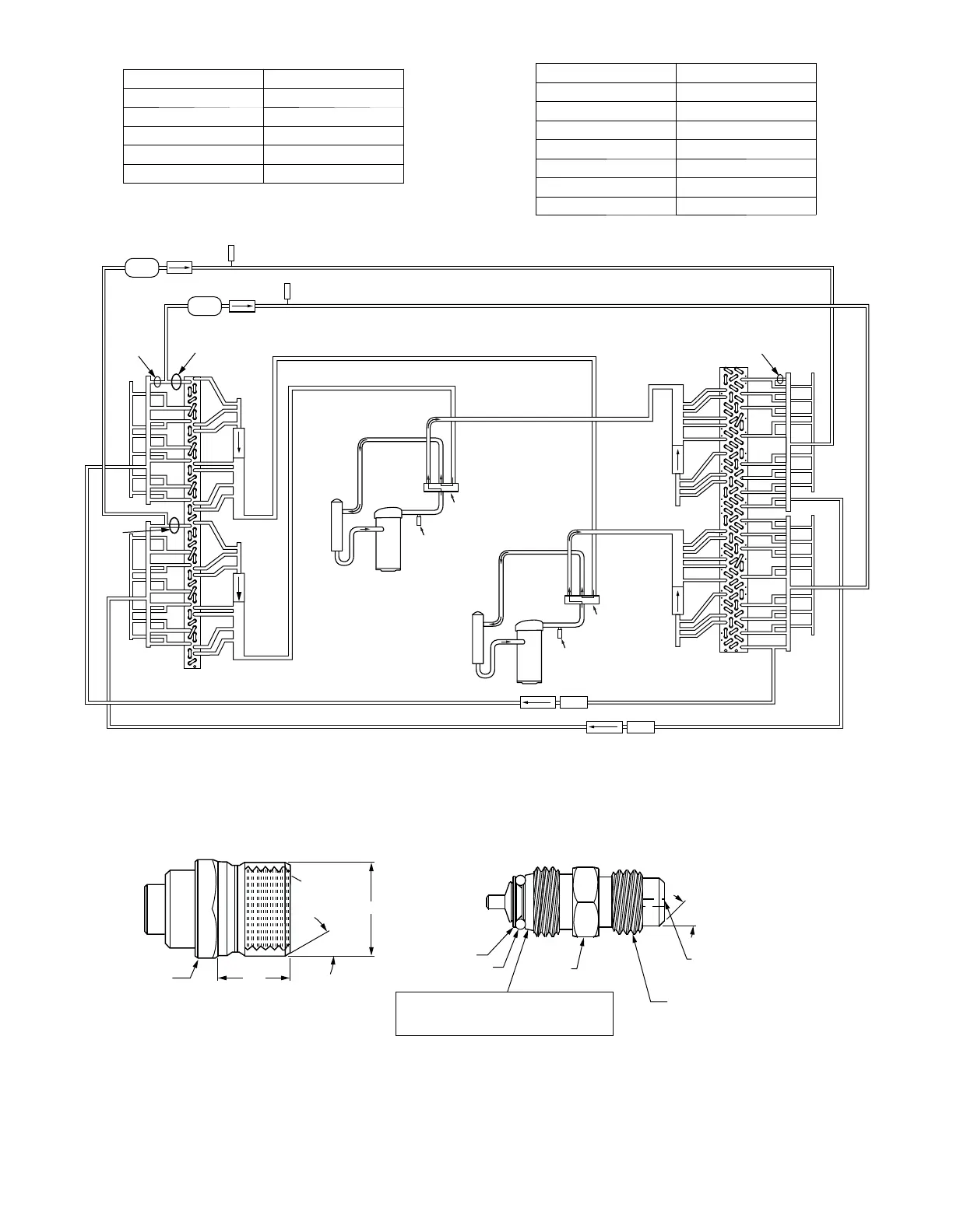
COMPRESSOR
ACCUMULATOR
HPS
COMPRESSOR
ACCUMULATOR
HPS
Filter
Drier
2B
1B
LPS/LOC
Acutrol
DFT 1
Cooling Liquid Lines
DFT 2
2A
1A
1D
2D
Outdoor Coil
Indoor Coil
Comp 2
Comp 1
2C
1C
Strainer
Heating Mode Liquid Lines
Acutrol
Reversing
Valve
Reversing
Valve
C09228
Fig. 5 -- Typical Unit Piping Schemati c (with TXV valves on Indoor Coils)
5/8” HEX
0.47
30°
0.596
1/2-20 UNF RH
1/2” HEX
45°
WASHER
O-RING
7/16-20 UNF RH
DEPRESSOR PER AHRI 720
+.01/-.035
FROM FACE OF BODY
This surface provides a metal to metal seal when
torqued into the seat. Appropriate handling is
required to not scratch or dent the surface.
SEAT CORE
(Part No. EC39EZ067)
a548J--- 009
Fig. 6 -- CoreMax* Access Port Assembly
* CoreMax is a registered trademark of Fastest, Inc.
 Loading...