52
the equipment, the maximum ventilation rate must be evaluated
for design conditions. The maximum damper position must be cal-
culated to provide the desired fresh air.
Typically the maximum ventilation rate will be about 5 to 10%
more than the typical cfm required per person, using normal out-
side air design criteria.
A proportional anticipatory strategy should be taken with the fol-
lowing conditions: a zone with a large area, varied occupancy, and
equipment that cannot exceed the required ventilation rate at de-
sign conditions. Exceeding the required ventilation rate means the
equipment can condition air at a maximum ventilation rate that is
greater than the required ventilation rate for maximum occupancy.
A proportional-anticipatory strategy will cause the fresh air sup-
plied to increase as the room CO
2
level increases even though the
CO
2
setpoint has not been reached. By the time the CO
2
level
reaches the setpoint, the damper will be at maximum ventilation
and should maintain the setpoint.
In order to have the CO
2
sensor control the EconoMi$er damper in
this manner, first determine the damper voltage output for mini-
mum or base ventilation. Base ventilation is the ventilation re-
quired to remove contaminants during unoccupied periods. The
following equation may be used to determine the percent of
outside air entering the building for a given damper position. For
best results, there should be at least a 10 degree difference in out-
side-air and return-air temperatures.
T
O
= Outdoor-Air Temperature
OA = Percent of Outdoor Air
T
R
= Return-Air Temperature
RA = Percent of Return Air
T
M
= Mixed-Air Temperature
Once base ventilation has been determined, set the minimum
damper position potentiometer to the correct position.
The same equation can be used to determine the occupied or max-
imum ventilation rate to the building. For example, an output of
3.6 volts to the actuator provides a base ventilation rate of 5% and
an output of 6.7 volts provides the maximum ventilation rate of
20% (or base plus 15 cfm per person). Use Fig. 68 to determine
the maximum setting of the CO
2
sensor. For example, an
1100 ppm setpoint relates to a 15 cfm per person design. Use the
1100 ppm curve on Fig. 68 to find the point when the CO
2
sensor
output will be 6.7 volts. Line up the point on the graph with the
left side of the chart to determine that the range configuration for
the CO
2
sensor should be 1800 ppm. The EconoMi$er IV control-
ler will output the 6.7 volts from the CO
2
sensor to the actuator
when the CO
2
concentration in the space is at 1100 ppm. The
DCV setpoint may be left at 2 volts since the CO
2
sensor voltage
will be ignored by the EconoMi$er IV controller until it rises
above the 3.6 volt setting of the minimum position potentiometer.
Once the fully occupied damper position has been determined, set
the maximum damper demand controlled ventilation potentiome-
ter to this position. Do not set to the maximum position, as this can
result in over-ventilation to the space and potential high humidity
levels.
CO
2
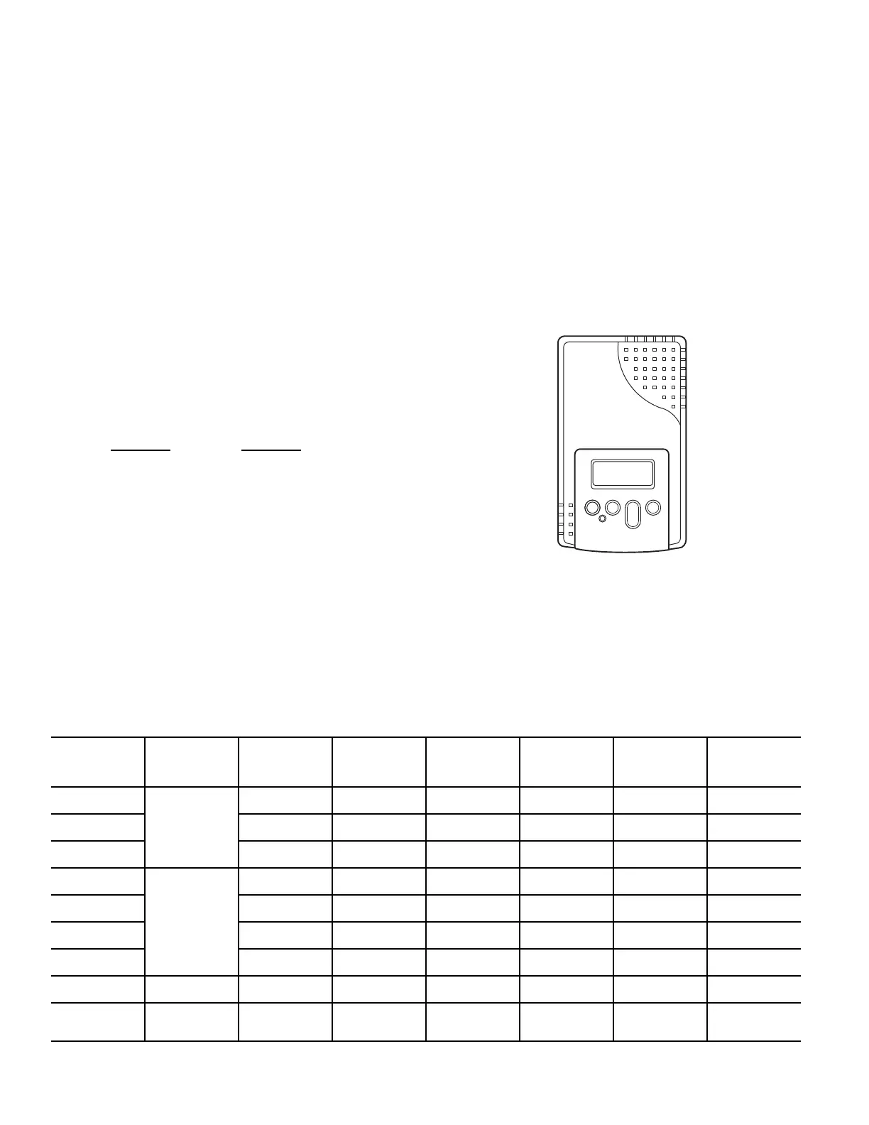
SENSOR CONFIGURATION
The CO
2
sensor has preset standard voltage settings that can be se-
lected anytime after the sensor is powered up. See Table 22 and
Fig. 69.
Fig. 69 — CO
2
Sensor
Use setting 1 or 2 for Bryant equipment. See Table 22.
1. Press Clear and Mode buttons. Hold at least 5 seconds
until the sensor enters the Edit mode.
2. Press Mode twice. The STDSET Menu will appear.
3. Use the Up/Down button to select the preset number. (See
Table 22.)
4. Press Enter to lock in the selection.
5. Press Mode to exit and resume normal operation.
(T
O
x
OA
)+ (T
R
x
RA
)= T
M
100 100
Table 22 — CO
2
Sensor Standard Settings
SETTING EQUIPMENT OUTPUT
VENTILATION
RATE
(cfm/PERSON)
ANALOG
OUTPUT
CO
2
CONTROL
RANGE (ppm)
OPTIONAL
RELAY
SETPOINT
(ppm)
RELAY
HYSTERESIS
(ppm)
1
Interface with
Standard
Building
Control System
Proportional Any
0-10V
4-20mA
0-2000 1000 50
2 Proportional Any
2-10V
4-20mA
0-2000 1000 50
3 Exponential Any
0-10V
4-20mA
0-2000 1100 50
4
Economizer
Proportional 15
0-10V
4-20mA
0-1100 1100 50
5 Proportional 20
0-10V
4-20mA
0-900 900 50
6 Exponential 15
0-10V
4-20mA
0-1100 1100 50
7 Exponential 20
0-10V
4-20mA
0-900 900 50
8
Health and
Safety
Proportional —
0-10V
4-20mA
0-9999 5000 500
9
Parking/Air
Intakes/Loading
Docks
Proportional —
0-10V
4-20mA
0-2000 700 50
 Loading...


