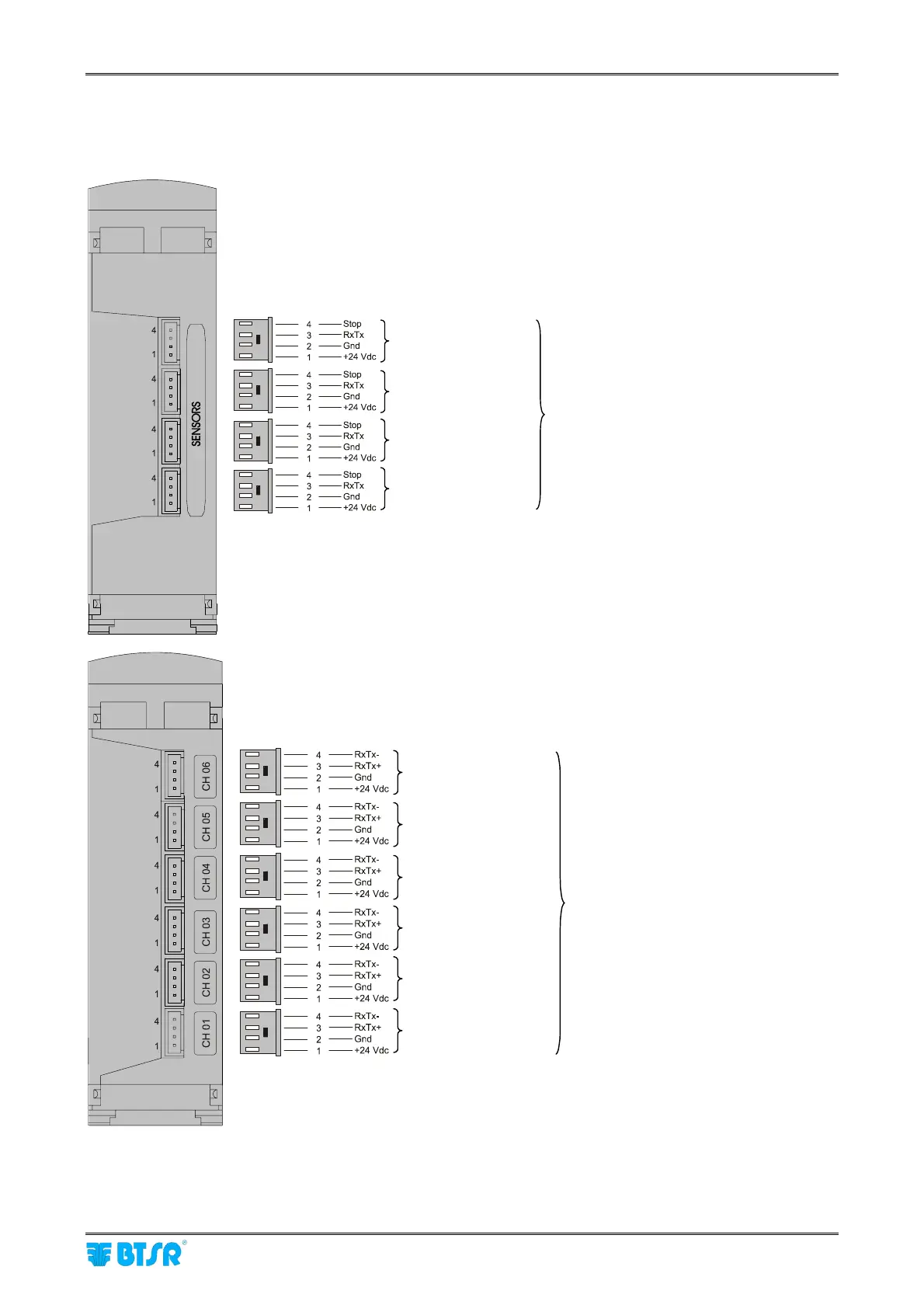
Sensors Interface
SMART MATRIX TWIST - 1-8 -
Sensor Interface
The following diagram shows the electrical interface (pin assignment) between SM-DIN and IS3.. sensors or
between ACT/Power module and IS3.. sensors
Max 64 IS3F/TTS sensors or
54 IS3W/TTS sensors
numbered with the Identify
function (Setup menu)
SM-DIN
Max 100 IS3F/TTS or
IS3W/TTS sensors
numbered with the Identify
function (Setup menu)
ACT/Power (optional)
Drop line 1 - Sensors
Drop line 2 - Sensors
Drop line 3 - Sensors
Drop line 4 - Sensors
Drop line 6 - Sensors
Drop line 5 - Sensors
Drop line 4 - Sensors
Drop line 3 - Sensors
Drop line 2 - Sensors
Drop line 1 - Sensors



 To Next Page