26
Installation and commissioning
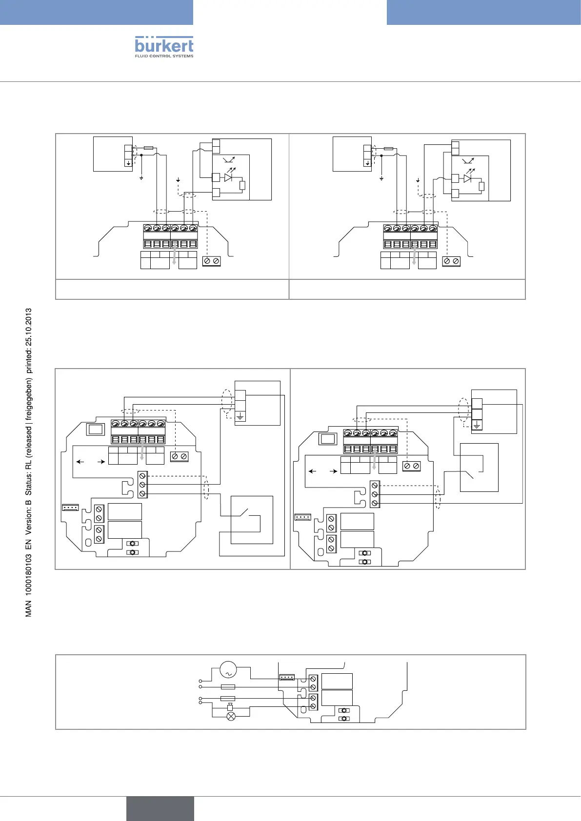
7.3.5. Wiring the DO1 transistor output
L+ L-PEP+P-Iout
Supply
18...36 Vdc
PULSE
DO1
PE
AO1
300 mA
+
-
18-36 V DC
(*)
+
-
+
-
5-36 VDC
PLC
Power supply
L+ L-PEP+P-Iout
Supply
18...36 Vdc
PULSE
DO1
PE
AO1
300 mA
(*)
+
-
+
-
5-36 VDC
+
-
18-36 V DC
Power supply
PLC
Fig. 22: NPN wiring of the DO1 transistor output Fig. 23: PNP wiring of the DO1 transistor output
*) If a direct earth connection is not possible, fit a 100 nF/50 V capacitor between the negative power supply terminal and the
earth
7.3.6. Wiring the DI1 digital input
SOURCESINK
L+ L-PEP+P-Iout
Supply
18...36 Vdc
PULSE
DO1
CURRENT
PE
DI1
PE
DO2
DO3
AO1
+
-
18-36 V DC
+
-
(*)
Power supply
Switch
Power supply
Switch
SOURCESINK
L+ L-PEP+P-Iout
Supply
18...36 Vdc
PULSE
DO1
CURRENT
PE
DI1
PE
DO2
DO3
AO1
+
-
+
-
(*)
Fig. 24: Possible wirings of the DI1 digital input
*) If a direct earth connection is not possible, fit a 100 nF/50 V capacitor between the negative power supply terminal and the
earth
7.3.7. Wiring the DO2 and DO3 relay outputs
DO2
DO3
230 VAC
m
3 A
3 A
230 VAC
Fig. 25: Wiring of the DO2 and DO3 relay outputs
English
Type 8045