Audio Trim: Allows fine trim of overall audio level, and right channel only, to
compensate for L/R imbalance.
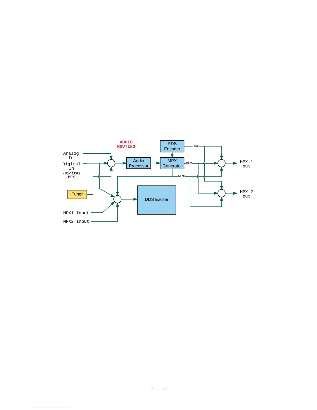
Note that if you set MPX Source (in RF Settings) to be MPX Input 1 or 2, the exciter is fed
directly from these rear-panel connectors, and the output of the audio processor and
internal mpx generator is ignored. However, the audio processor and mpx generator are
still running, and the generated mpx signal can still be routed to the MPX 1 and or 2
output connectors.
Bearing this in mind, if you wish to use an external RDS generator which needs to be fed
with an mpx signal, you can route the mpx output from the MPX OUT 1 connector to the
external unit, and loop back to the V3 transmitter’s MPX 1 input connector. In this case,
you would set Input Source to MPX Input 1.
The following diagram may help to explain the audio routing available:
7.3 MPX
The V3 transmitter incorporates a stereo coder, otherwise known as an mpx generator
(‘mpx’ meaning multiplex, sometimes known as ‘composite’).
The stereo generator includes a composite clipper. With a drive setting of 0dB, this has
no effect; above that it will become active and clip the mpx signal. The clipper contains
RDS/SCA protection filters, also there is a pilot protection filter option.
The audio clipper protects the mpx generator from peak excursions and overshoots in
the source audio. It is distortion-cancelling and anti-aliased.
Furthermore, there is an ‘overshoot compensator’ which handles any overshoots from
the main clipper, and restricts the audio bandwidth to 15kHz.
Note: The mpx generator is fed from the audio processor; the selection of which input to
use is made within the Audio Settings menu (see section 7.2).