Do you have a question about the C-COR.net FlexNet E7 and is the answer not in the manual?
Provides an overview of the FlexNet 700 Series Line Extender models.
Explains document typeface usage and notes, cautions, and warnings.
Details FCC, CE, and UL compliance for the device.
Lists other relevant documents and their numbers.
Lists required tools, equipment, and materials for operation and maintenance.
Illustrates the physical layout and components of the E7 Line Extender with HE PSU.
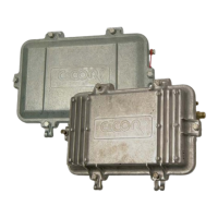
Shows the physical layout and components of the E7 Line Extender with Linear PSU.
Depicts the physical layout and components of the E75 862MHz ALC Line Extender with IPS.
Displays the physical layout and components of the E77 862MHz Line Extender with 117VAC PSU.
Illustrates the physical layout and components of the E73 Line Extender with 117VAC PSU.
Shows the physical layout and components of the E629 Line Extender.
Details steps for inspecting and preparing the housing before installation.
Provides instructions on how to properly open the diecast aluminum housing.
Describes different methods for mounting the E7 Line Extender housing.
Explains the procedures for attaching coaxial cables to the line extender ports.
Details the steps for correctly closing and tightening the housing for a weatherproof seal.
Outlines procedures for setting up and testing the power supply options.
Explains how to calculate forward high balancing carrier levels using a specific formula.
Describes how to perform temperature compensation for aerial coaxial cable.
Details procedures for balancing the forward RF signal path of the line extender.
Explains procedures for balancing the return RF signal path of the line extender.
Provides instructions for installing active return upgrade kits.
Introduces procedures for checking operational characteristics of a suspected faulty line extender.
Offers steps to quickly determine if an amplifier is causing a forward path signal outage.
Guides users on troubleshooting power supply issues based on voltage testing.
Details procedures to verify the forward signal levels and gain of the line extender.
Explains how to verify the return signal levels and gain of the line extender.
Describes routine checks for damaged parts and loose connections during maintenance.
Provides instructions for safely removing and installing fuses or slugs.
Details the procedure for replacing the RF module in the line extender.
Outlines steps for replacing the High Efficiency power supply module.
Explains how to replace the entire housing of the line extender.
Presents detailed RF module specifications for various E7 Line Extender models.
Lists power supply options and corresponding housing types for E7 Line Extenders.
Provides physical dimensions and weight for E7 Line Extender housings.
Details input and output signal levels and frequencies for FlexNet 700 Series models.
Shows the functional block diagram for the standard E7 Line Extender.
Illustrates the block diagram for the E75 862MHz model with ALC.
Displays the block diagram for the E7 862MHz/117VAC model.
Presents the functional block diagram for the E629 Line Extender.
Explains methods for using reference tables to select balancing accessories.
Describes how to install plug-in accessories like equalizers and attenuators.
Contains tables for cable equalizers and simulators, and attenuators.
Section for recording system map details like map number, system, and location.
Area to record signal levels, TCV, and balancing carrier information.
Field to note pre-selected accessories like Interstage EQ.
Section for recording technician-selected accessories like Forward/Reverse EQ/PAD.
Fields for recording forward and reverse signal levels at different testpoints.
Area to record power supply type, fuse values, and voltages.