Rev F Troubleshooting Test Procedures 5-3
5
Forward Path Field Testing
This procedure verifies that the E7 Line Extender:
■ is balanced to the correct forward signal levels
■ delivers the specified gain to forward RF signals
These procedures require the use of a signal level meter (SLM). A more comprehensive test involves
sweeping the entire bandwidth with an appropriate sweep generator/receiver—especially desirable
when response problems are suspected.
➤ To field test the forward path
1. If present, set the ALC/MAN switch to the MAN position.
2. Connect an SLM to the Port 1 external testpoint and measure the input signal levels of both
forward balancing carriers. Verify that the input signal levels are within reasonable tolerance
of the measurements made during the initial balancing procedure. If not, find the cause of
the variation external to the line extender. Correct if necessary, then rebalance the line
extender.
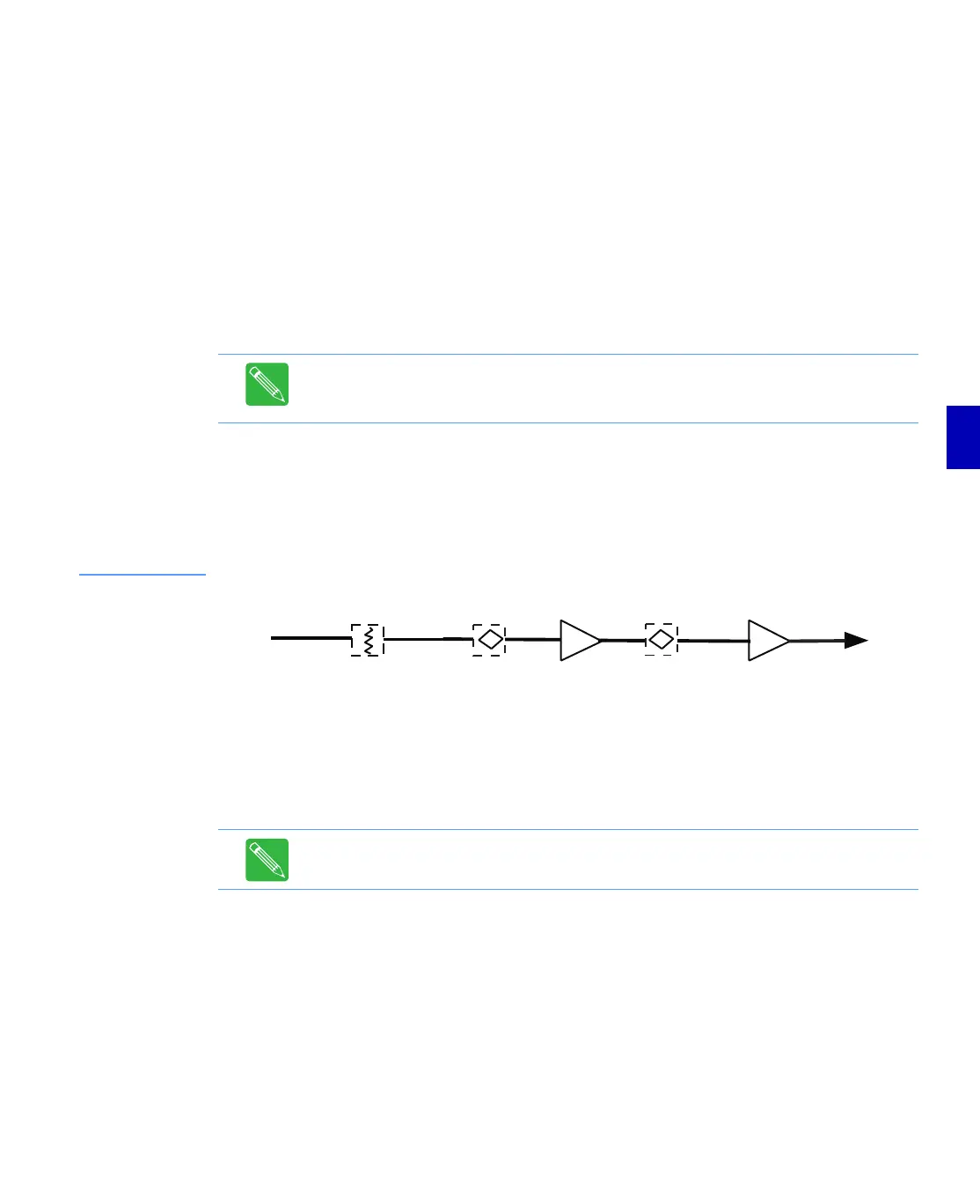
Figure 5.1
Simplified Forward
Path Block Diagram
3. Connect a SLM to the Port 3 external testpoint and measure the output signal levels of both
forward balancing carriers. Compare the present levels to the measurements made when the
line extender was previously balanced. If the current measurements are unacceptable, verify
that the proper accessories or striplines are still installed in all forward plug-in locations and
replace any accessories not in compliance with the FlexNet® 700 Series Line Extender Data
Sheet. If necessary, rebalance the E7 Line Extender.
4. Calculate the true E7 Line Extender gain by subtracting the input high balancing carrier signal
level measured at Port 1 from the output signal level measured at Port 3. The difference
should equal the operational gain of the line extender (at the balancing carrier) minus
insertion losses from accessories installed in the forward path. Refer to When the Equalization
Value is Known on page C-1 to determine insertion losses at the high carrier frequency.
Replace the RF module if the E7 Line Extender gain measured at any port is out of tolerance.
5. If present, reset the ALC/MAN Switch or TLC/MAN Switch to ALC or TLC.
6. If necessary, adjust the ALC Sensitivity control as described in Forward Balancing Procedure
on page 4-8.
Note: All measured signal levels must be temperature compensated to a common
temperature before they can be accurately compared. Refer to Temperature
Compensation on page 4-5 for information on temperature compensation.
Note: The Operational Gain listed on a C-COR Amplifier Specification Sheet is the gain
at the high bandedge frequency and includes 1dB of loss for the forward equalizer.
Port 1
Port 3
FORWARD PAD FORWARD EQ INTERSTAGE EQ