5-4 FlexNet
®
700 Series Line Extender Rev F
5
Return Path Field Testing
This procedure verifies that the E7 Line E extender:
✔ is balanced to the correct return signal levels
✔ provides the specified gain of return RF signals
The following procedure requires the use of a SLM. A more comprehensive test involves sweeping the
entire bandwidth with an appropriate sweep generator/receiver—especially when response problems
at specific frequencies are suspected.
➤ To field test the return path
1. Connect a signal generator to the Port 3 external testpoint. Set the signal generator to output
the correct Return High Balancing Carrier Level +25dB (to overcome testpoint loss) at the
proper frequency.
2. Connect a signal level meter to the Port 1 external testpoint and measure the output signal
level of the Return High Balancing Carrier. Compare the current level to the measurements
made when the line extender was previously balanced. If the current measurement is
unacceptable, verify that the proper accessories or striplines are still installed in all return
plug-in locations and replace any accessories not in compliance with the Line Extender Data
Sheet. If necessary, rebalance the line extender.
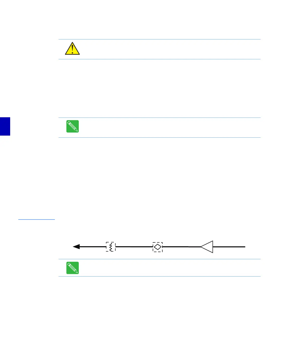
Figure 5.2
Simplified Return
Path Block Diagram
3. Calculate the true return line extender gain by subtracting the input signal level (set in Step 1)
from the output level measured at Port 1. The difference should equal the operational gain
of the line extender (at the balancing carrier) minus insertion losses from accessories installed
in the return path. Refer to When the Equalization Value is Known on page C-1 to determine
insertion losses at the high carrier frequency. Replace the RF module if the line extender gain
measured at Port 1 is outside of acceptable tolerance.
CAUTION: RF signal levels greater than +30 dBmV @ 1 NTSC channel loading at the
hybrid can damage amplifier active components. Do not use test signals greater than
+30dBmV at the hybrid (+30dBmV = 90dBµV).
Note: All measured signal levels must be temperature compensated to a common
temperature before they can be accurately compared. Refer to Temperature
Compensation on page 4-5.
Note: The Operational Gain listed on a C-COR Amplifier Specification Sheet is the gain
at the high bandedge frequency and includes 1dB of loss for the return equalizer.
Port 1
Port 3
REVERSE PAD REVERSE EQ