Rev F Configuration 4-21
4
Completing the Installation
All E7 Line Extenders require the same procedures for completing the upgrade.
➤ To complete return kit installation (all kits)
.
1. Position the faceplate on the RF module and secure it using the screws removed in To prepare
for return upgrade kit installation (all kits) on page 4-16.
2. Install the RF module and close the housing, referring to the instructions in Housing Opening
on page 3-4 and RF Module Replacement on page 6-2 necessary.
3. Verify the performance of the E7 Line Extender on both the forward and return paths. For
field-test procedures, refer to:
■ Forward Balancing on page 4-8
■ Return Balancing on page 4-12
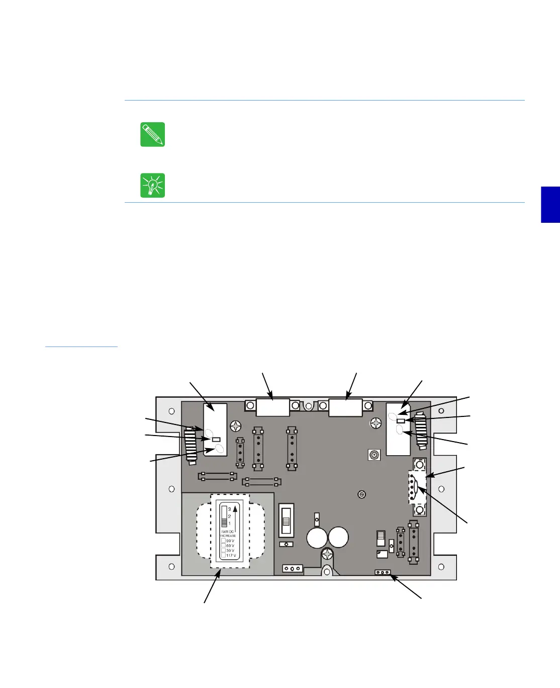
Figure 4.9
E7 Motherboard
Note: After the installation of a Return Hybrid, E7 Line Extender performance should be
verified. Realignment of the minimum return loss at 42 and 54 MHz by adjusting the
diplex filter coils may be necessary. Refer to the specification sheet for your particular
line extender.
Note: C-COR recommends this as a bench procedure.
Tip: Marking the faceplate of a modified E7 Line Extender may assist future maintenance
efforts.
Output Diplex Filter
Location
Input
Diplex Filter
Location
Forward
Input Hybrid
Forward
Output Hybrid
Return
Hybrid
Location
Capacitor
(only on
models with
passive return)
Regulator Installation Area
(not present on models
with H.E. power supply)
Transformer (linear power supply) or
Power Plug connector for H.E. power supply
C59
C55
L22
C60
L19
C54