6–20
Chapter 6: PLC Communications
6
EA1-MG6-USER-M Hardware User Manual, 1st Ed. Rev C, 09/10
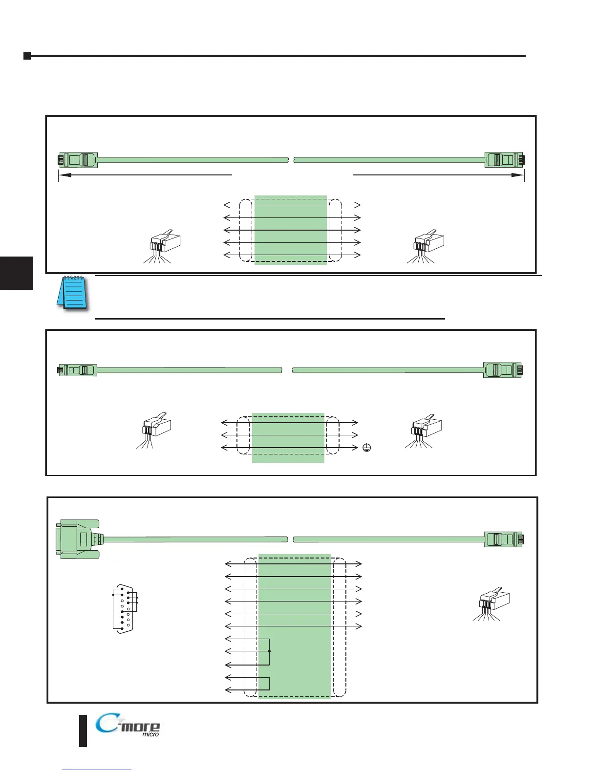
Cables from AutomationDirect – Wiring Diagrams (cont’d)
Note: Only one C-more Micro-Graphic panel can be powered by an AutomationDirect PLC. If connecting
C-more Micro-Graphic panels to more than one port on and AutomationDirect PLC, the additional panel
must use an external power supply.
Direct
Logic PLC RJ11 port: D3-340 Port 1 & 2
RS-232C (p/n OP-3CBL-1)
To PLC
RJ11 Port
1
1 = RXD
2 = TXD
3 = do not use
4 = Sig GND
2
4
RXD
TXD
GND
4
3
1
TXD
RXD
RJ11 4-pin
Phone Plug
(4P4C)
Wiring Diagram
Note: Use the above wiring diagram if you need to make your own cable. We recommend using 22 AWG shielded cable.
1 2 3 4
To C-more
Micro-Graphic
Serial Port1
1 = Sig GND
2 = not used
3 = RXD
4 = TXD
5 = +5 VDC
6 = Sig GND
1 2 3 4 5 6
RJ12 6-pin
Phone Plug
(6P6C)
To C-more
Micro-Graphic
Serial Port1
DirectLogic DL405 PLC Port 0: DL-450 Port 0
RS-232C (p/n D4-1000CBL)
To DL405 PLC
Port 0
6
4
15
3
Wiring Diagram
3
2
1
14
1 2 3 4 5 6
RJ12 6-pin
Phone Plug
(6P6C)
1 = GND
2 = do not use
3 = RXD
4 = TXD
5 = +5 VDC
6 = GND
2
12
5
11
7
13
8
4
1
8 = YOM Sense
7 = CTS
6 = do not use
5 = do not use
4 = Online
3 = RXD (232C)
2 = TXD (232C)
1 = YOP Sense
15 = Logic GND
14 = Logic GND
13 = Logic GND
12 = do not use
11 = do not use
10 = do not use
9 = do not use
1
15
15-pin
D-sub
(male)
See PLC user manual
for pin out details.
GND
RXD
TXD
GND
YOP
CTS
YOM
GND
5V
TXD
RXD
GND
Power Supplied to Panel through Cable from CLICK and Direct
Logic PLC RJ12 port:
DL05, DL105, DL205, DL350, DL450, H2-WINPLC
RS-232C (p/n DV-1000CBL)
To PLC
RJ12 Port
To C-more
Micro-Graphic
Serial Port1
6
4
GND
TXD
1
3
GND
Wiring Diagram
3
RXD
2
+5 V
1 = Sig GND
2 = not used
3 = RXD
4 = TXD
5 = +5 VDC
6 = Sig GND
1 2 3 4 5 6
RJ12 6-pin
Phone Plug
(6P6C)
1
GND
6
GND
1 2 3 4 5 6
RJ12 6-pin
Phone Plug
(6P6C)
1 = Sig GND
2 = +5 VDC
3 = RXD
4 = TXD
5 = not used
6 = Sig GND
4
5
RXD
TXD
+5 V
10 feet [3.0 m] Maximum