Troubleshooting
The following are some problems that may be encountered during the installation and
operation of your C-more
®
Micro-Graphic panel. We have made some suggestions on
what to check in order to correct the problem.
C-more 6” Micro-Graphic Panel does not Power up
Powered from 5 VDC: If the panel’s display is blank, not responding, and the panel is powered
from a 5 VDC power source such as a PC or PLC, check the incoming DC voltage level with
a voltmeter. The DC voltage level should be in the range of 4.75 to 5.25 VDC. If the incoming
DC voltage is zero, check any fusing that may be in the circuit. If the fuse is open, determine
cause and replace.
Powered from 12-24 VDC: If the panel’s display is blank, not responding, and the panel is
powered from a 12-24 VDC power source, check the incoming DC voltage level to the adapter
with a voltmeter. The DC voltage level to the adapter should be in the range of 10.2-26.4 VDC.
If the incoming DC voltage is zero, check any fusing that may be in the circuit. If the fuse is
open, determine cause and replace.
Display is Blank
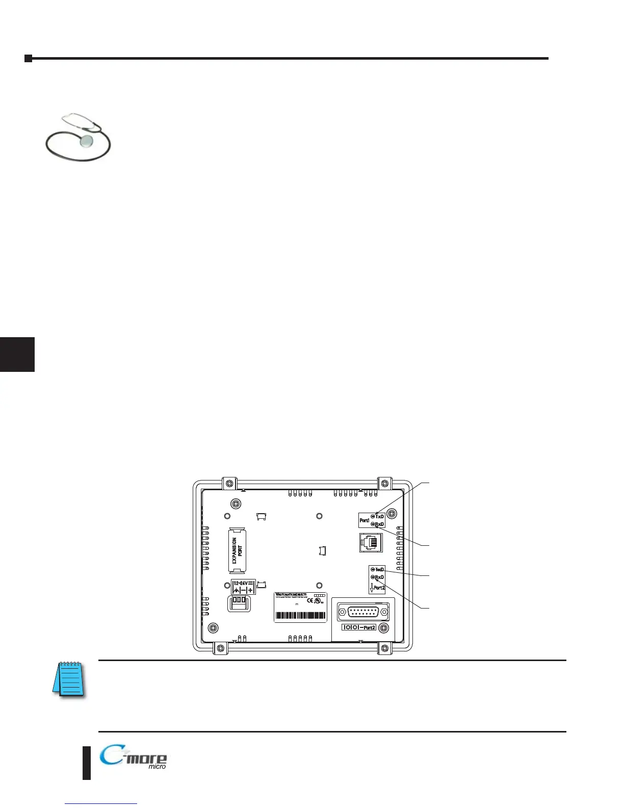
Also if the panel’s display is blank, check the TxD and RxD indicators on the back side of the
panel while the panel is communicating with the PLC. The LED indicators should be on or
flashing at a fast rate. Indicator activity shows that the panel is communicating with the PLC.
If there is communication activity, but the display is still blank, there is the possibility the
program in the PLC is controlling the display. Try pressing the F1 and F5 keys simultaneously
for 3 seconds. The panel will change to the System Setup Screen menu if the screen is being
forced to display a blank screen by the PLC program. Also, check the PLC program, it may have
the screen in the off state by placing a 0 in the current screen tag.
8–2
Chapter 8: Troubleshooting
NOTE: When the panel is powered through Port1 from a connected PLC or PC, the screen brightness is
diminished because the panel is running in Low-Power Mode. For full brightness, connect an external
12-24 VDC power source to the panel’s power connection. Low-Power Mode is intended for initial
programming. For full brightness, connect an external 12-24 VDC power source when the panel is installed
in its application..