6–26
Chapter 6: PLC Communications
EA1-MG6-USER-M Hardware User Manual, 1st Ed. Rev C, 09/10
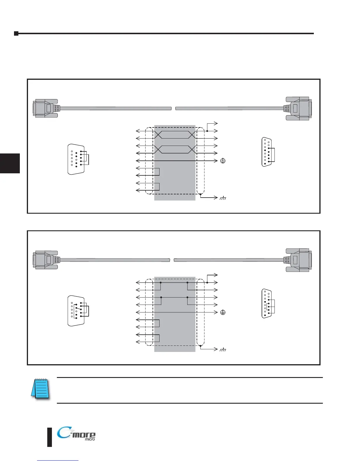
User Constructed Cables – Wiring Diagrams
Diagram 1
Diagram 2
Direct
LOGIC DL06, D2-250, D2-250-1, D2-260
(all Port 2) RS-422A
To PLC
15-Pin Port
Wiring Diagram
Note: Use the above wiring diagram to make your own cable. We recommend Belden 8103 shielded cable or equivalent.
9
10
7
TXD+
TXD–
GND
9
10
5
1
RD+
RD–
shield
RXD+
RXD–
13
6
11
12
SD+
SD–
Term.
13
8 = do not use
7 = do not use
6 = do not use
5 = Logic GND
4 = do not use
3 = do not use
2 = do not use
1 = Frame GND
15 = do not use
14 = do not use
13 = Termination
12 = SD– (RS422)
11 = SD+ (RS422)
10 = RD– (RS422)
9 = RD+ (RS422)
1
15
15-pin
D-sub
(male)
12
RTS–
14
CTS+
15
CTS–
11
RTS+
15-pin
HD D-sub
(male)
8 = do not use
7 = Sig GND
6 = RXD–
5 = do not use
4 = do not use
3 = do not use
2 = do not use
1 = do not use
15 = CTS–
14 = CTS+
13 = RXD+
12 = RTS-
11 = RTS+
10 = TXD–
9 = TXD+
1
6
15
To C-more Micro-Graphic
Serial Port2
Direct
LOGIC DL06, D2-260 (both Port 2)
RS-485A
To PLC
15-Pin Port
Wiring Diagram
Note: Use the above wiring diagram to make your own cable. We recommend Belden 9842 shielded cable or equivalent.
13
9
7
RXD+
TXD+
GND
9
11
5
1
RD+
SD+
shield
TXD–
RXD–
10
6
10
12
RD–
SD–
Term.
13
8 = do not use
7 = do not use
6 = do not use
5 = Logic GND
4 = do not use
3 = do not use
2 = do not use
1 = Frame GND
15 = do not use
14 = do not use
13 = Termination
12 = SD– (RS485)
11 = SD+ (RS485)
10 = RD– (RS485)
9 = RD+ (RS485)
1
15
15-pin
D-sub
(male)
12
RTS–
14
CTS+
15
CTS–
11
RTS+
15-pin
HD D-sub
(male)
8 = do not use
7 = Sig GND
6 = RXD–
5 = do not use
4 = do not use
3 = do not use
2 = do not use
1 = do not use
15 = CTS–
14 = CTS+
13 = RXD+
12 = RTS-
11 = RTS+
10 = TXD–
9 = TXD+
1
6
15
To C-more Micro-Graphic
Serial Port2
NOTE: The RS-422 and RS-485 wiring diagrams shown above are not for multi-drop networks involving
connecting more than one PLC to a panel. Refer to the wiring diagram examples starting on page 6-38 if more
than one PLC will be connected to a panel.
User Constructed
User Constructed